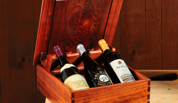
A good friend celebrated a milestone birthday this year, and since he’s a real wine afficionado, I wanted to give him a few very nice bottles of wine presented in a special way. I’ve seen expensive vintage wines sold in wooden presentation boxes, but I wanted to make something that’s well beyond the ordinary. So I designed a box that presents the wine bottles by “popping them up” as the lid is opened.
Most of this project is a very straightforward build and requires no special hardware. The box itself has sides joined with dovetails and a solid wood bottom set into a groove. The hinged lid is made with a mitered frame that holds a floating raised panel. The bottle lifting mechanism attaches to the underside of the lid and has a pair of bullet catches that keep the lid in the open “presentation” position when it’s fully lifted. The top Special beverages given as a gift deserve a special presentation. This box features a unique mechanism that literally “pops up” three wine bottles as the lid is opened. of the lifting mechanism, as well as a bottle rack at the bottom of the box, keep the three bottles aligned and prevent them from shifting or clunking together. My box is proportioned to hold regular wine bottles, but you could adapt it to hold other kinds of bottles or containers.
Resawing the Stock
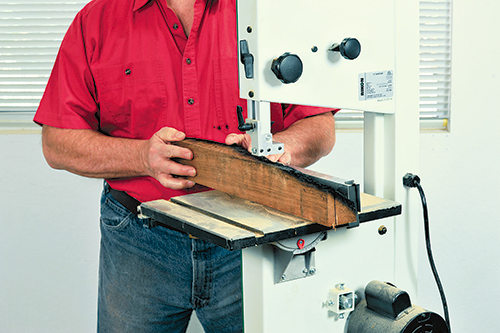
The box, as shown in the Drawing, is mostly made out of 1/2″-thick stock. Since I didn’t have any stock that thin on hand, I decided to cut a couple of 2′-long bolts from one of the first-growth redwood stumps on my property in California’s Santa Cruz Mountains. These trees are more than a thousand years old and yield wood that’s a beautiful reddish-brown color with very tight grain (it’s also much harder than newer redwood lumber). I resawed the bolts on my band saw and produced more than enough 1/2″ stock for my project, as well as a few pieces of 1/4″ stock to glue up for the box’s bottom. While most of the stock was quartersawn, I plainsawed (cut parallel to the tree’s annular rings) the bolt with the most attractive grain figure, to use for the box lid’s raised panel.
Building the Box
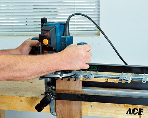
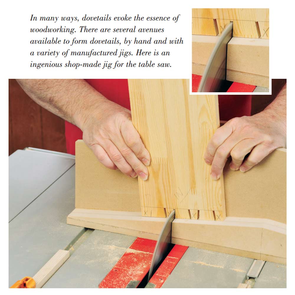
Once all the parts were cut to the dimensions shown in the Material List, I set about building the basic box itself. To make the box more attractive, I chose to join the sides with dovetails cut using a router and an adjustable finger-style dovetail jig. Alternatively, you may choose box joints or miter the corners together. After spacing the jig’s fingers to create three full pins and two half pins across the width of the sides, I cut test pieces using stock scraps, tweaking the jig until it produced perfect, tight dovetails. I marked the outside face and orientation of each piece, to help assure that the joints would be cut correctly, then routed the pins on both ends of the box’s front and back pieces using a router fitted with a collar bushing and straight bit. I then cut the four matching tails in both ends of the box’s left and right side pieces using an 8˚ dovetail bit in the router. For both cuts, I set the depth of the bit so that the pins/tails ended up slightly proud of the surface with the joint assembled.
Next, I cut the groove on the inside of all four box sides, to hold the box’s bottom. I did this on the router table using a 1/4″ spiral-fluted straight bit. I set the table’s fence so the groove would end up 1/4″ from the bottom edge of each side and set the bit’s cutting depth so the grooves would be just over 1/4″ deep. To prevent the grooves from showing through at the dovetail-joined corners, each cut had to be started and stopped just shy of the end of the stock. I did this by marking the stock’s start and stop positions on the table fence, then dropping and lifting the stock at the beginning and end of each cut.
To make the box bottom, I planed several narrower pieces to a final thickness a hair under 1/4″, jointed their edges square, then glued them up to create a 12-3/8″-wide bottom. Once the glue was dry, I scraped off the squeeze-out, then trimmed the bottom to its final dimensions. I sanded the bottom, as well as the inside faces of the box sides, down to 240-grit sandpaper, in preparation for assembly. I took care not to sand the dovetail surfaces, lest I spoil their fit.
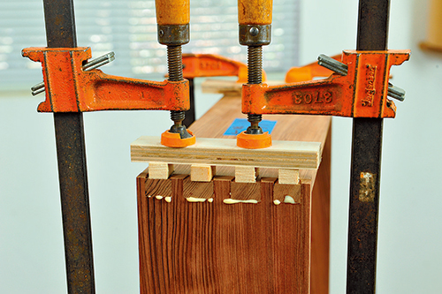
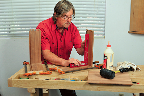
I assembled the sides of the box in two steps: First, I glued up the right side of the box with the front, applying yellow glue to all joint surfaces before carefully pressing the corner together. Before clamping, I arranged four small pine blocks over the tails, then set a larger block over them, to apply pressure only where it’s needed to clamp the joint together. I repeated this procedure with the box’s left side and back, then used a try square to check that parts were square.
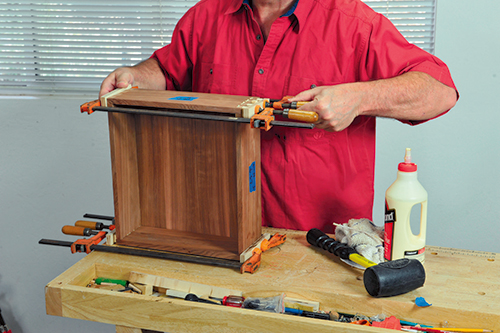
After these subassemblies dried, I glued them together while simultaneously capturing the bottom in its groove. It helps if you trim off just the very tips of the bottom’s corners so they’ll slip into place more easily. After applying the clamps, I checked the box for square before setting it aside to dry.
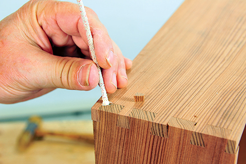
Once the glue squeeze-out was rubbery hard, I belt-sanded each side of the box until the slightly protruding pins and tails were flush. Upon careful inspection, I discovered a few places where corners of the tails had broken away, leaving unsightly gaps. I repaired the smaller gaps with filler mixed from redwood dust and glue; for bigger gaps, I carefully cut redwood plugs that I glued in place. Once the joints were perfect, I finish-sanded all the outside surfaces and edges of the box.
Making the Lid
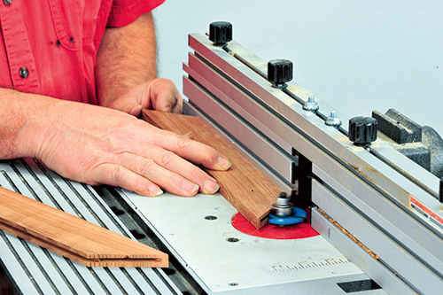
The lid for the box is made much in the same way I’d make a frame-and-panel door for a cabinet project. The frame has 45˚ mitered corners joined with plate joinery biscuits. A groove on the frame’s inside edge holds a panel whose edges have been “raised” (shaped to be thinner at the edge to fit the groove). After cutting the frame stock to width, I mitered the ends on the table saw, using a sliding miter jig to assure that the ends were all a perfect 45˚. I also made sure that the opposite pairs of frame members were exactly the same length. I then used the router table fitted with a 5/32″ slot cutter bit to slot the ends of the miters for #10 plate joinery biscuits. I set the table’s fence so that slots were centered on the mitered ends. I then used the same bit to rout a 5/32″ wide, 3/8″-deep groove on the inside edge of each frame piece for the center panel.
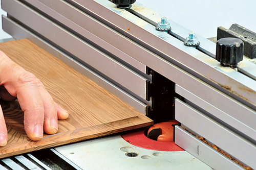
As mentioned earlier, I cut some highly figured redwood pieces for the lid’s center panel. For a decorative look, I glued together two narrower pieces that were consecutively cut from the bolt to create a book-matched panel with a mirror-symmetrical grain pattern. Once the panel was glued up, scraped and sanded, I cut it to final dimensions, then shaped its edges on the router table. In lieu of a traditional panel-raising bit, I used a finger pull bit, the top portion of which created the desired 1/4″ radius cove cut (a cove bit also works fine). I set the bit’s height to leave 1/8″ of thickness after the panel’s edge had been shaped on both sides. To avoid grain tearout, I routed the shorter ends of the panel first, then the longer edges. After shaping both sides of the panel, I sanded all surfaces smooth.
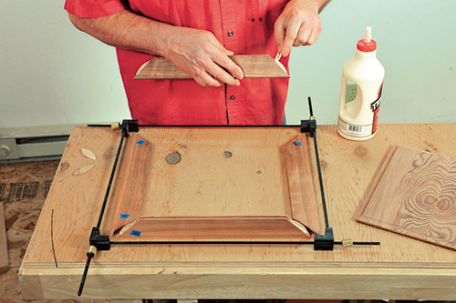
To assemble the box lid, I applied glue to all the biscuits and slots on the ends of the miters. I assembled one corner first, set the panel into its groove, and then put the remaining frame members in place. To make the process easier, I used a quick-release frame clamp set, which keeps all four corners aligned as it applies clamping pressure. I scraped off any squeeze-out after the glue had dried. To add detail to the lid, I shaped a small cove around the entire top edge of the frame and then sanded both sides of the frame to final smoothness.
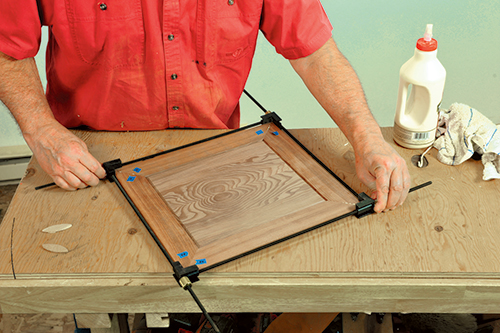
The lid is attached to the box with three small brass hinges. ,After centering the lid atop the box, I clamped it temporarily in place, then inverted the assembly on my benchtop (atop an old towel, to prevent dings and scratches) and positioned hinges as shown on the Drawing. After marking and drilling pilot holes, I drove all 12 screws to secure the hinges in place.
Forming the Lifting Mechanism
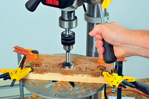
As these three holes are centered only 1/8″ from the edge, I temporarily clamped on a scrap strip to keep the bit aligned during drilling. I rounded over both edges of each notch with a 1/4″-radius roundover bit in a small router. Next, I drilled a 3/8″ hole in each end of the vertical support strips (for the bullet catches) as well as a single countersunk 1/8″ hole through each of the mounting blocks.
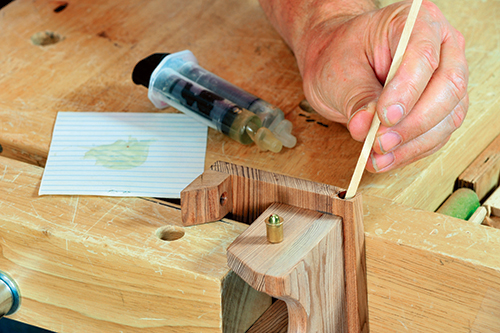
Assembly of the lifting mechanism takes a few steps. First, I attached the six dividers to the top of the lifting strip, with the two end dividers flush with the ends of the strip. The other four are aligned adjacent to the edges of the notches, as shown in the Drawing. After applying just a touch of glue to each divider, I carefully positioned it square to and flush with the strip’s back edge, then clamped it down. Once this assembly dried, I glued it to the front of the vertical support strip, locating it 1/4″ up from the support strip’s bottom edge and centering it lengthwise. I also glued the mounting blocks and reinforcing strip in place.
When everything dried, I strengthened the connections between parts with 1″-long pins driven with a pneumatic pin gun. Next, using my oscillating spindle sander, I rounded over the corners of the notches in the lifting strip, so their outer edges come flush to the dividers. Finally, I fitted the two bullet catches, gluing each into its hole with just a dab of two-part epoxy.
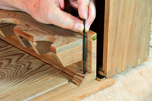
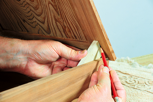
To mount the lifting mechanism, I started by using a scrap block to mark a line on the underside of the lid that’s in line with the inside of each of the box’s sides. I set the box upside down atop a towel on the benchtop and opened the box so it stood upright. I then placed two shim strips, one 1/2″ thick, the other 3/32″ thick, against the edge where the box’s hinges are. I set the lifting assembly onto the lid and centered it between the marks I just made. With the mechanism’s back edge pressed against the shims, I slipped a sharpened piece of wire into the mounting block holes to mark their positions. I then used the marks to drill small pilot holes for the #6 x 1 screws, repositioned the lifting mechanism and screwed it into place.
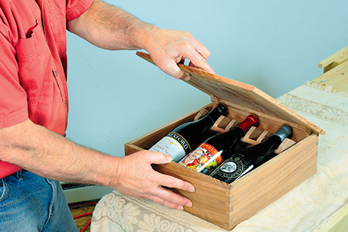
After flipping the box over, I closed the lid, using a pair of scrap blocks to depress the bullet catches. After making sure the mechanism functioned properly by testing it with three wine bottles, I positioned the lid with the bullet catches about 1/2″ below the top edge of the box, and marked their positions. Using a Dremel tool fitted with a 1/4″-diameter round burr, I created a shallow dimple at each bullet catch mark, then tried the mechanism again: The lid should click and stay in position when the catches engage the dimples. To make it a little easier for the catches to disengage when closing the box, you may want to sand or file a slight “ramp” on the lower side of each dimple. The last step is to unscrew the lifting mechanism, apply glue to its top edge, and screw it back onto the lid.
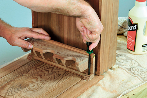
There’s just one more part to add: the bottle rack to hold bottles. After cutting it to size, I sawed out three 31/2″-diameter semicircles on the band saw, then went over the edges with a 1/4″-radius roundover router bit. I glued and nailed the rack to the bottom of the box, positioning it parallel to and 1-1/2″ from the box’s front side. To finish my presentation box, I applied several coats of Danish oil, which revealed the redwood’s grain figure beautifully. I then waxed the outside surfaces to bring them up to a bright semi-gloss finish. Now all that’s left is to pick out three really good bottles of wine to put into the box!
Hard to Find Hardware
3/4” x 3/4” Butt Hinges, Brass #49165
3/8” Bullet Catches #28464
Click Here to Download the Drawings and Materials List for This Project.
