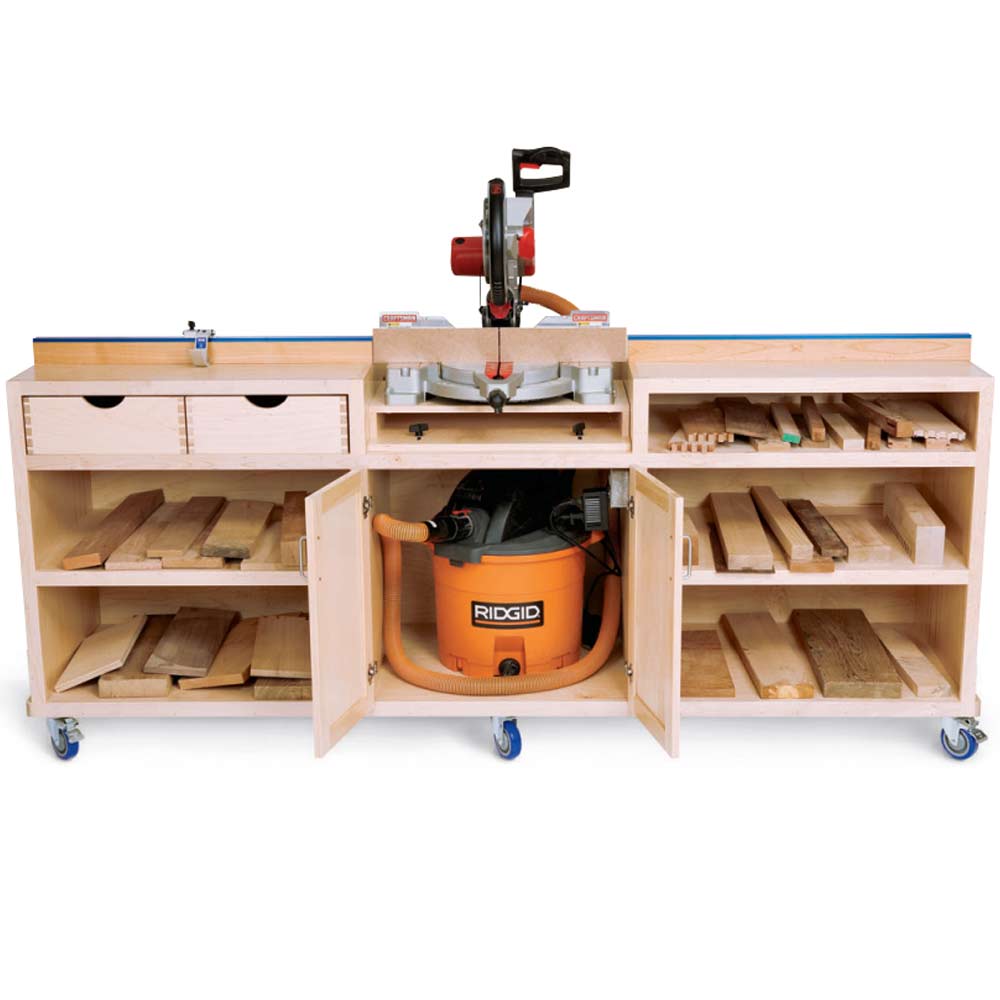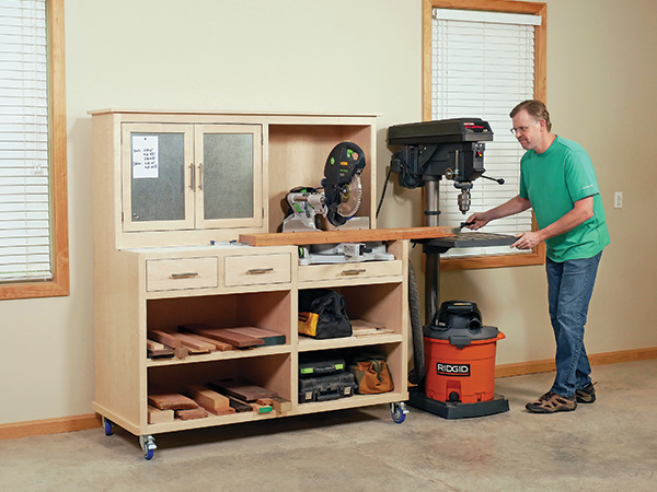
A miter saw station I built for our June 2010 issue became our most popular shop project in Woodworker’s Journal’s history. But 10 years of regular use have provided a “punch list” of improvements I’ve been itching to incorporate into an updated design. For one, at 8 ft. long, it dominated wall space and was a battleship to roll around. This second go-around is much shorter, at 64-1/4″, because I’m using my drill press table as the right-hand support surface for crosscutting long workpieces. There’s still plenty of shelf space for offcuts or general storage, plus two drawers that I’m planning to use for stowing valuable short scraps. You won’t find a long fence beside the saw either; it really isn’t necessary and sometimes can actually hinder safe crosscutting of distorted wood. That fence typically includes a work stop to make repetitive crosscuts easier, but here the feature is taken care of with an aluminum T-track and Corner Stop from Rockler. I’ve also come to the realization that miter saws need both active dust collection (via shop vacuum or dust collector) and a passive way to capture what suction inevitably doesn’t. So this station has a chamber behind the saw to help contain floating dust as well as a pull-out tray below that you can dump or vacuum out when needed. (It’s also a nifty way to recover those pesky little offcuts that can get trapped under a saw if it sits on a solid platform rather than on a couple of support blocks as it does here.) My first design collected a hodgepodge of shop clutter behind the long fence. On this “Miter Station 2.0,” I’ve integrated an upper cabinet with steel-clad doors to fill that space. It offers dedicated storage plus a way to hang your notes or plans within easy view, using magnets.
Making the Carcass
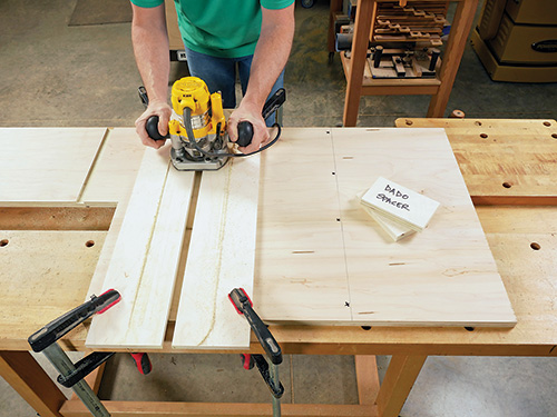
sandwich a couple of spacers of the project plywood in order to create
exact-fitting dadoes in the uprights.
Get this station underway by cutting the bottom panel to size. Then download our elevation drawings so you can lay out and cut the four uprights to shape from 3/4″ plywood. Label them A through D, to index them from left to right on the final assembled project. Carefully glue and clamp uprights C and D together so their edges and ends align to create a double-thick upright. Rout 3/4″-wide, 1/4″-deep dadoes across the appropriate faces of the uprights for the upper cabinet bottom panel, wide and narrow shelves and web frame. Here’s the dado schedule:
- Upright A: Dadoes for the upper cabinet bottom, web frame and wide shelf in the right face.
- Upright B: Dadoes for the upper cabinet bottom in the left face and two narrow shelf dadoes in the right face.
- Upright C/D: Two narrow-shelf dadoes in the left face.
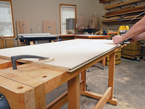
Cut the wide and narrow back panels to size. These are differently sized so that their shared seam will be hidden behind upright B when assembled. Rip and crosscut a pair of solid-wood edging strips to hide the outer edges of the two back panels. Glue and clamp them in place. If you have a biscuit joiner, a few #20 biscuits can help to align the parts and make the clamping process easier. When the glue dries, plane or sand the edging flush with the plywood faces as needed.
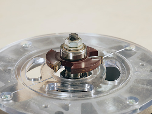
Plow a 1/4″-wide, 1/2″-deep groove along the inside edges of the back panels that will house a continuous spline. I used a slot-cutting bit in a handheld router for the task. Plane a strip of 1″-wide stock down to 1/4″ thick to create the spline. Or, use 1/4″ plywood for the spline instead, as I did. Either way, make sure the spline fits easily but snugly in the panel slots.
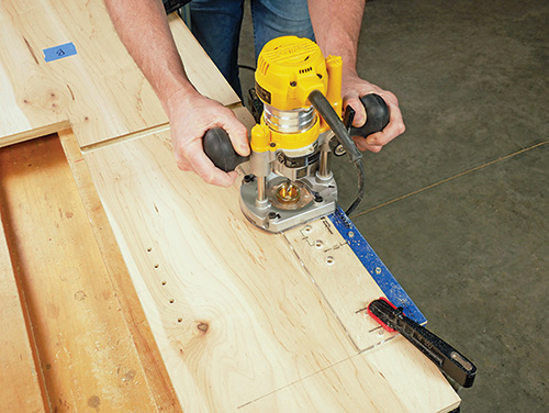
Decide where you want the shop vacuum hose to pass through the miter station in what will become the chambered area behind the saw, and determine how large this hole needs to be to suit your shop vac hose. For my saw, I chose upright C/D for this “pass-through” hole, but a hole through the back panel might be a better choice for some saws. Bore the hole now. I cut mine with a 2-1/2″-diameter hole saw in a drill press. While you’re at it, mill two rows of 1/4″-diameter shelf pin holes into the right face of upright A and the left face of upright B within the upper cabinet area so you’ll have plenty of adjustment options for a shelf. When that’s done, arrange and fasten the uprights to the top face of the bottom panel with countersunk 2″ screws. Locate upright B so its left face is 34-1/4″ from the left end of the bottom panel.
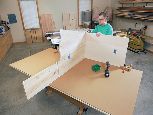
Now you can install both halves of the back panel on the carcass, joining them along the middle seam with the spline glued in place. Fasten the back panel to the uprights and bottom panel with counterbored 2″ screws. The bottom end of the back panel should extend 3/4″ past the bottom face of the bottom panel. Make sure upright B is also centered on the back panel’s splined seam.
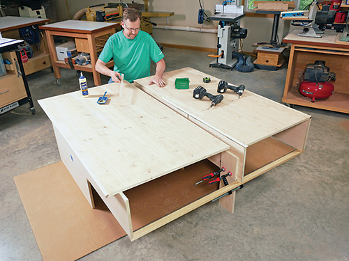
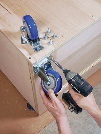
Rip and crosscut the short and long bottom cleats to size, and install them with glue and countersunk screws or brad nails. Align the outer edges of the cleats carefully with the bottom panel edges. While the project is still lying down, locate and mount the four casters on the bottom cleats. I positioned the caster mounting plates flush with the outside edges of the bottom cleats. Arrange the locking casters in front and the non-locking casters in back. Bolt them on and stand the project up on its wheels.
Cut the plywood top panel to size, and glue strips of short and long solid-wood trim to its ends and edges to hide the edge plys. When the glue dries, install the top on the carcass with 2″ counterbored screws. The ends of the top panel should overlap the outer uprights by 1″. Its front edge should overlap the front edges of the uprights at this stage by 1-3/4″.
Head back to your stack of plywood to cut the narrow shelves, wide shelf, a panel for the web frame and the shelf supports to size. Make two large cutouts in the web frame panel that form a pattern of 2″-wide “stiles” and “rails” around its perimeter and across the center. The purpose of this web frame is to form an attachment point for the drawer divider and to enable easier access inside the drawer compartments for installing the slides, later.
You can also cut plywood panels to shape for the drawer divider and the upper cabinet’s bottom panel. Make the notched portion of the drawer divider measure 3-1/4″ x 12-1/4″. Now dry fit the wide and narrow shelves, web frame, upper cabinet bottom and drawer divider in the carcass to make sure they are ready for installation. Then remove and finish-sand them.
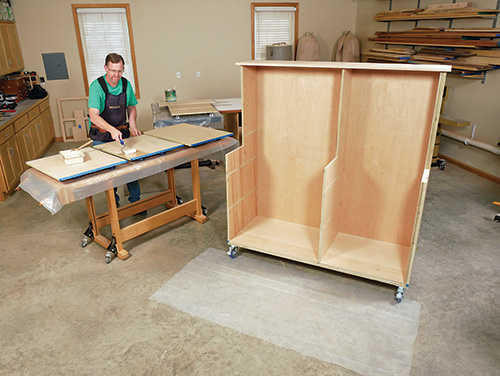
While you still have easy access to the carcass’s inner surfaces, now is a good time to apply finish to it, as well as to the shelves and upper cabinet bottom panel. But first, mask off the ends of those parts that will fit into dadoes to keep finish off of these areas. On the left face of upright B, keep the full area below the dado for the upper cabinet bare — you’ll be gluing the shelf supports to these surfaces. As you apply finish, keep it out of the dadoes and off of the ends and back edges of the cleats and bottom panel — the skirt boards will need to be glued to these surfaces after a few more steps.
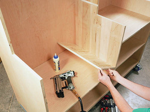
When the finish dries, glue the narrow shelves into their dadoes in uprights B and C. Glue the wide shelf and web frame into their dadoes in upright A. Spread glue on the shelf supports and set them into place against upright B so they straddle the right ends of the wide shelf and web frame.
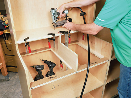
Now install the upper cabinet bottom into its dadoes. Slide the drawer divider into place; be sure its front end is flush with the front edge of the web frame. Carefully center the divider between uprights A and B and along the length of the upper cabinet bottom panel. Attach the divider by driving 18-gauge brads down through the upper cabinet bottom panel and countersunk screws up through the web frame.
Adding the Face Frames and Work Surface
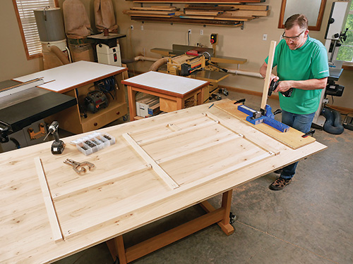
The lower face frame consists of two end stiles, a middle stile and a short drawer stile, three long rails, two short rails and a bottom rail. Rip and crosscut these parts to size from solid wood, but make the end stiles about 1/16″ wider than the other members. Doing this will give you a bit of extra left-to-right adjustability when installing the face frame on the carcass.
Arrange the parts into the face frame shape on a large work surface, and mark the joints for pocket screws. Assemble the rails and stiles carefully, connecting the parts with pairs of 1-1/4″ pocket screws at each joint.
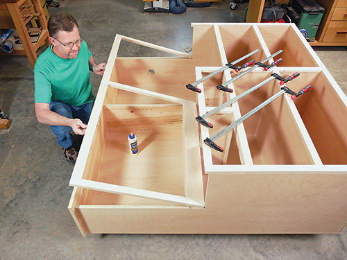
Set and clamp the face frame into position on the front of the carcass, adjusting it so the middle rail covers upright B and the shelf supports; adjust the bottom rail flush with the bottom faces of the bottom cleats. If everything fits well, glue and clamp the face frame to the carcass. You can reinforce the glue joint with brad nails, if you wish. Repeat the process to assemble and install the upper face frame. Make its end stiles a bit wider than necessary, and take note that the top rail for this face frame is 2″ instead of 1-1/2″.
When both face frames are in place, trim their end stiles flush with the outer uprights using a block plane or sanding lock. Rip and crosscut the short bridge rail, and glue it to upright C/D between the upper and lower face frames.
The side and back skirt boards hide the long and short cleats and bottom panel from view. Make these skirt boards from strips of 3/4″ x 1-/2″ solid stock. I rounded the outer corners of the side skirt boards with 3/4″ radii at my disk sander to help them stand up better to wear and tear. Install the side skirt boards on the carcass so their front ends are flush with the front of the lower face frame. Glue and brad-nail them in place. Then fit and install the rear skirt board with more glue and brad nails.
The drawer slide hardware will be mounted on filler strips located inside the drawer openings. These filler strips enable the slides to be installed flush with the inside edges of the face frame stiles. A pair of thin filler strips attach to either side of the drawer divider, and a thicker filler strip is located on upright A and B. Measure the amount of actual recess behind the face frame for each of the four filler strips, and prepare stock to match these recesses at your thickness planer. Rip and crosscut the strips to size. Install them on the uprights and divider with countersunk 1-1/4″ wood screws, centering the filler strips vertically in their drawer openings.
Next up, cut a panel for the work surface to size. You can use ordinary plywood for this workpiece, of course, but consider the option of white melamine or covering the work surface with plastic laminate. Either material will enable you to mark the work surface with a pencil when crosscutting multiple pieces to the same length, then wipe off the marks when you’re through. It’s a nice convenience to have. Glue and clamp a strip of solid-wood edging to the ends of the work surface. I reinforced these joints with three #20 biscuits per end to keep them aligned during clamping.
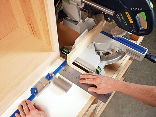
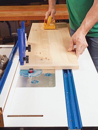
When the glue dries, plow a 3/4″-wide, 3/8″-deep groove into the top face of the work surface to fit a T-track. Position this groove so the T-track will be located 1″ behind your miter saw’s fence (or sacrificial fence facing, if you use one) when the saw is installed in the station. To determine the groove’s location, set the work surface and your saw temporarily in place on the project. Raise the saw on scrap blocks until the saw’s table is flush with the work surface. Use a long straightedge, held against the saw fence, to register where the T-track will need to be. Then cut the groove with a dado blade at the table saw or on your router table with a 3/4″-wide straight bit. Cut a piece of aluminum T-track to fit the full length of the work surface groove. Install it on the work surface with short flathead wood screws, making sure they don’t protrude beyond the work surface into the drawer compartments below.
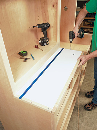
Go ahead and install the work surface on uprights A and B with countersunk 1-1/2″ screws driven down through the edging strips and into the uprights. I decided to leave these screw heads exposed, in case wear-and-tear on the work surface should ever make me want to replace it in the future.
The upper cabinet still needs a shelf, so cut one to size, and glue a strip of solid wood to its front edge to hide the edge plys. Plane or sand the edging flush to the shelf faces when the glue dries. Apply finish to the shelf, then mount the shelf inside the upper cabinet on four shelf pins.
Your miter saw’s base will stand on and be attached to a pair of saw supports that consist of top and bottom blocking pieces with two risers in between. The blocking pieces need to be wide enough to enable you to bolt or screw your saw base to them with the blocking also flush against uprights B and C/D. Set your saw back in the compartment to determine the correct blocking width for your saw base, then cut the four blocking pieces to width and length.
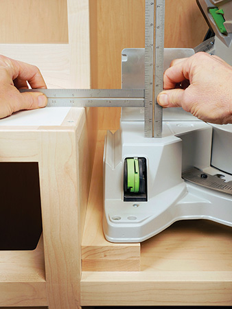
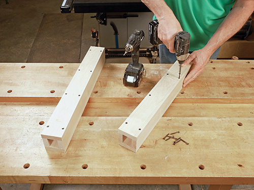
The height of the four risers will also vary, depending on the working height of different miter saw bases. To determine the correct width for your saw, stack the blocking face to face in pairs and set them in place in the station. Set the saw on these stacks. Now measure the height from the saw table to the work surface; this measurement determines the riser width. Cut the risers to width and length, then assemble the four parts of each saw support with glue and brad nails or screws.
Final-sand and apply finish to the face frames, saw supports and any other bare surfaces at this point to complete them. When it dries, set the saw supports into place in the saw compartment. Attach them by driving countersunk screws through the upper narrow shelf from below and into the bottom blocking of the supports.
Building the Drawers
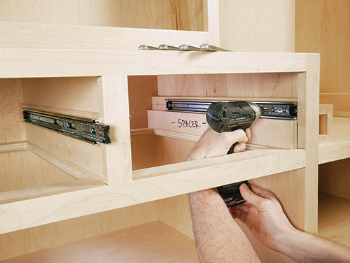
It’s time to install the drawer slides in their openings. To do that, unclip the cabinet-side components of the slide hardware from the drawer-side components. Position the cabinet-side components on their filler strips so the hardware will be centered in the drawer openings, vertically. The front ends of the slides should be flush with the back edge of the face frame. To make sure the slides will be parallel with one another, set them in place on a scrap spacer before driving the attachment screws to secure them. Choose the horizontally slotted holes in the slides so you can move the hardware forward or backward slightly, if needed, when the drawers are hung.
Reinstall the drawer-side components of the slides onto the cabinet-side components, and measure the distance between the slides for each drawer. This measurement sets the final length of the drawer fronts.
Rip and crosscut enough 1/2″-thick stock to make the fronts, backs and sides for both drawers. For now, leave the drawer backs overly long. Make up a couple of test pieces to help you refine your joint-cutting setups in the next step, too.
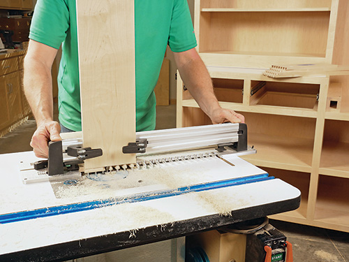
I used a dovetail jig to rout half-blind dovetails for joining the box fronts to the sides. Be sure to rout test pieces first, to fine-tune your jig’s settings, before milling the actual parts.
The drawer backs fit into 1/2″-wide dadoes that are located 1/4″ in from the back inside faces of the drawer sides. Cut these dadoes at the table saw or router table. Then switch to a 1/4″-wide dado setting or a 1/4″ straight bit so you can mill grooves in the drawer sides and fronts for the drawer bottom panels. These grooves are 1/4″ deep. Position them so they’re hidden inside the lowest tail sockets of the drawer fronts and behind the lowest tails of the drawer sides.
Go ahead and dry fit the drawer sides on the drawer fronts and square up the corners carefully in order to verify the final length of the drawer backs. Cut the backs to length, slide them into place on the drawer boxes and take a final measurement for the drawer bottom panels. (The back end of the bottom panels will extend to the back faces of the drawer backs.) Cut the bottom panels to size from 1/4″ plywood.
Final-sand the parts before gluing and clamping the two drawer boxes together. Do this carefully, measuring their diagonals before the glue sets to make sure the drawer boxes are square. When the drawers come out of the clamps, drive a few 1″ brads up through the drawer bottoms and into the drawer backs to fix the bottoms in place. Give the outside surfaces of the drawers a final sanding, as needed, to flatten the dovetailed surfaces.
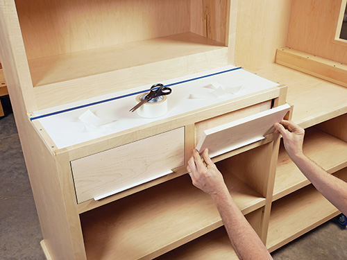
Your drawers are ready for hanging! Lay out the drawer slide locations on the drawer sides, and install the slides on the drawer boxes with screws. The front ends of the slide components should be flush with the drawer fronts. Connect the slides again, and test their action to make sure the drawers open and close smoothly. If they do, rip and crosscut a couple of drawer faces from 3/4″ stock. Size the drawer faces to allow for about 1/16″ of clearance all around when the faces are installed in the drawer openings. Final-sand the drawer faces, then position the faces on the drawers temporarily with pieces of double-sided tape. When you have them located and adjusted to your satisfaction, drive several #6 x 1″ screws through the drawer fronts and into the drawer faces to secure them. Mark the faces for drawer pulls, and install the hardware with long screws driven into them from inside the drawers. Tweak the drawer slide positions, if needed, so the drawer faces close flush and fit evenly. Then you can install more screws into the slides to lock their positions.
Adding Steel-clad Cabinet Doors
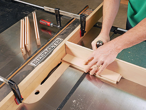
Cabinet doors don’t have to be hard to build, and I’ve kept these easy for any skill level. The corner joints are 3/8″-long stub tenons on the ends of the rails that fit into 3/8″-deep grooves in the stiles. This same groove is milled along the inside edges of all four stiles and rails to receive the door panels and a facing of 24-gauge galvanized sheet steel.
Start by ripping and crosscutting the four stiles and rails from flat, straight 3/4″-thick stock. Then carefully measure the combined thickness of the sheet metal and the plywood you’ll be using for the two-piece drawer panels. This thickness determines the actual width of the rail-and-stile grooves as well as the final thickness of the stub tenons on the rails. Plow a 3/8″-deep, centered groove along one edge of each rail and stile with a stacked dado set to match the panel thickness you need or by making two cuts with a standard blade. Make a test cut first on scrap stock that matches your rail-and-stile thickness to confirm your blade and rip fence settings.
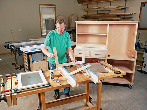
Now stack a wide dado blade to mill 3/8″-long stub tenons on the ends of the rails. Make these cuts with the rails backed up with your miter gauge equipped with a sacrificial fence to reduce tearout. When the sawing is done, dry fit the door frames together to inspect the corner joints, as well as to take inside width and length measurements for the final panel sizes. Cut the plywood and sheet metal to these proportions. Carry out another dry fit with the plywood and sheet metal installed; make sure the corner joints still close properly. Final-sand the face of the plywood panels that will show when the doors are opened, then glue and clamp each door together. When the doors come out of the clamps, final-sand the frames and fit them in the cabinet opening. Trim their edges and ends at the joiner or with a hand plane, as needed, to create even clearance all around when they’re hung.
I mounted my doors to the face frame with no-mortise hinges to give this project the look of classic cabinetry while also making the door-hanging process easy. To install them, locate and attach the hinge leaves to the face frame stiles with pairs of screws driven into the slotted holes of the hinge leaves. Set each door in its opening, marking the hinge leaf locations on its back face. (It helps to set a thin spacer between the bottom edge of the door and the bottom face frame rail to maintain swing clearance while you mark the hinge locations.) Carefully drill centered pilot holes for the hinge leaf screws, and attach the leaves to the doors to hang them. Adjust the doors up and down, or from side to side, as needed to create even spacing between them — slotted holes in the hinge hardware provide some helpful adjustability here.
When my doors hung evenly, I could really see the end of this big project in sight! I’ll bet you will, too. But we’ve got some ground to cover before we’re through. So remove the doors and bore holes for the pull hardware, then give them a final sanding and apply finish. You can rehang them when the finish cures. Glue a block of scrap behind the top rail so you can mount a simple magnetic door catch to it for each door.
Making the Pull-out Saw Tray
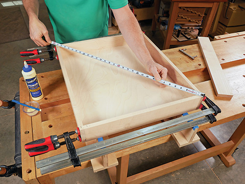
The tray, which captures debris below the saw, is joined at the corners with simple rabbet-and-dado joints. Rip and crosscut the tray front, back and sides from 1/2″ solid stock. The length of the tray front and back should be 1/2″ less than the span between the inside faces of the saw supports.
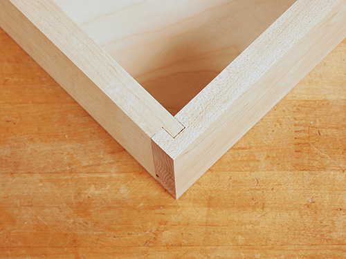
Mill the tray’s corner joints by cutting 1/4″ x 1/4″ rabbets into the ends of the tray front and back. The tray sides require 1/4″-wide dadoes to receive the rabbet tongues; position these dadoes 1/4″ in from the ends of the parts. You can cut these joints on either a table saw or router table, but be sure to test your setups on scrap stock before machining the actual tray parts. If the joints fit together well, mill a 1/2″-wide, 1/4″-deep groove along the inside faces of the tray front, back and sides for a bottom panel. Dry assemble the tray frame to double-check the proportions of the bottom panel, and cut one from 1/2″ plywood. Finish-sand the parts, then glue and clamp the tray with the bottom panel in place. Be sure it remains square.
Rip and crosscut a face for the tray from solid wood, giving it about 1/16″ of clearance inside the saw compartment opening. Set the tray in place between the saw supports, and position and clamp the face to the tray so the face fits its opening evenly. Drive countersunk 1″ screws through the tray front and into the face to secure it. Then install a centered drawer pull on the face, just as you did for the drawers.
I applied several strips of 3/4″-wide Nylo tape to the narrow shelf alongside the saw supports. They stretch the full frontto- back length of the tray opening and enable the tray to slide in and out almost as easily if it was mounted on metal slides.
Helpful Hardware Finishes Things Up
I installed a pair of plastic 2-1/2″-diameter grommets on each side of the vacuum hose opening I cut in the right upright of my miter station. The grommets add a nice finished touch to this pass-through, hiding the cut edges in the plywood.
Set your miter saw in position, and make sure it will swivel fully, left to right, without contacting the back or side walls of the chamber. I drove screws down through my saw’s base mounting holes and into the saw supports to secure it.
Two pieces of hardware can add even more convenience to this project. First, Rockler’s 2-1/2″ O.D. Dust Right Coupler enables me to attach my shop vacuum to the miter saw’s dust hose conveniently. I used a short length of Rockler’s Flexiport hose and two adapters from its Power Tool Hose Kit to connect the saw to the coupler. This way, my shop vacuum can be used for miter saw dust collection or detached quickly and easily for other clean-up duties around the shop.
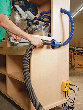
Another handy accessory is an iVac outlet switch (yellow in photo). With both the saw and shop vac plugged into it, turning on the saw automatically starts the shop vac. The iVac keeps the shop vac running for an extra 5 seconds after the saw is turned off to clear any remaining dust.
Add a workpiece stop to the T-track of your new miter saw station, and this saw-enhancing project is finished! Now roll it into position next to your drill press, plug it in and enjoy the added convenience it brings to your miter saw’s operation.
Click Here to Download the Drawings and Materials List.
Hard-to-Find Hardware:
4″ Polyurethane Casters, Total-Lock Swivel (1) #23030
4″ Polyurethane Casters, Swivel Plate Mount (1) #22410
4′ Universal T-track (1) #20054
100-lb. Full-extension Drawer Slides, 20″ (4) #69876
Satin Nickel Ball-tip Full Wrap Inset Hinges (2) #27505
Narrow Profile Magnetic Catch (2) #26559
Hopewell Bar Pull 3-3/4″, Satin Nickel (5) #1010954
1/4″ Shelf Supports, Nickel (1) #22773
2-1/2″ Brown Grommets (2) #51100
Nylo-tape, 3/4″ W x 10′ L (1) #59739
Dust Right® 2-1/2″ Mountable Dust Coupler (1) #54955
Dust Right® FlexiPort Power Tool Hose Kit (1) #51170
iVac Dust Collector Switch Box (1) #42884
T-track Corner Stop (1) #58673
