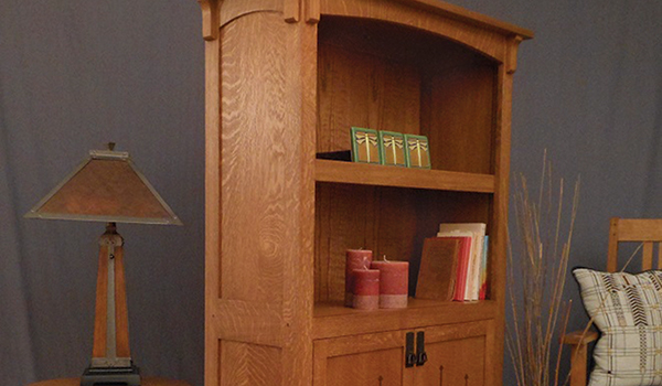
This Arts & Crafts style bookcase is modest in size, yet large enough for functional storage. Unlike typical purchased bookcases, it’s made with more hardwood than plywood. I built this case from quartersawn white oak; however, cherry would look great as well. It features two inset doors, graced with a series of delicate inlays, plus a top with a slight overhang (1-3/4″ on the top and sides; 1″ on the back). The hardware includes hammered bail pulls classic to the Arts & Crafts style, and fully adjustable spring-closing hinges.
Locking Miter Joints
The side assemblies are a good place to get started, and I began by milling enough stock for the entire project. Pay particular attention to the long boards that will form the front legs. Make sure this stock is straight, and rip two consecutive 2-1/8″-wide strips from the same board. This way, you will be rewarded with grain that wraps seamlessly around the front legs when you’re through. Starting with these strips slightly wider than needed is a good idea, so they can later be edge jointed and ripped to the finished width of 2″. Also add three to four inches of extra length so you can trim off any router snipe that may occur while routing the locking miters. Treat them as if they were a tabletop glue-up; their edges should align without forcing them together. Mark the pairs of workpieces with the edge to be milled for a locking miter joint.
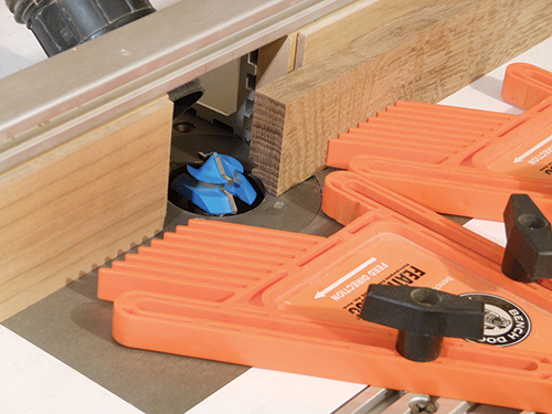
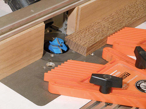
Take the leg strips to the router table and set up a locking miter bit. I used a shop-made setup block, but if one is unavailable you will need to make a few test cuts. Start by raising the locking miter bit 1/16″ above the workpiece thickness. Make small adjustments to the fence or bit height until you are satisfied with the fit. Set the router fence and bit depth and lock them in. These settings will not change again.
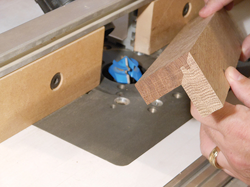
It is often said that locking miter joints need to be cut in one pass, which in fact is not true. In my experience, routing locking miters in two passes will reduce chipout and yield a cleaner finished cut, and here’s how it’s done: Use double-sided carpet tape to adhere spacers to the router fence. The spacers are nothing more than 1/4″-thick MDF or hardboard. Now make the first pass on each leg component. Remember that one piece is milled flat on the router table, while the adjoining piece is held vertically against the router fence. Then simply remove the spacers from the fence, and make a second pass to remove the remaining waste material.
This is a good time to glue up the front legs, and it’s during this stage that we see the real benefit of locking miters. Use thick cauls and clamp the joint together. Since the locking miter is self-aligning, clamping pressure only needs to be applied in one direction.
While the legs are drying, turn your attention to the side panels. I made the side panels from 3/4″ oak, and planed them down to 1/2″ thickness after the glue dried. These small panels will fit through most planers, and it saves considerable sanding that way. While the panel clamps are out, go ahead and make up the door panels and top panel as well.
Cut a full-length groove in the legs to receive the side panels. Trim the legs to final length and mark the location of three mortises on each leg. Now chop those mortises 1″-deep using a hollow-chisel mortiser. The grooves guide the chisel for perfectly centered mortises. With the same setup at the mortiser, make one additional mortise on each of the front legs to receive the long top rail (see the Drawings).
The side assemblies are straightforward with mortise-and-tenon construction. The tenons of the top and bottom rail are haunched to fill the long groove in the legs. The only hiccup is that the top rail is curved. This means you must first shape the top rail to the desired curve, before cutting the groove in its edge. I chose a curve with a 7/8″ deflection at the apex. After the top rail curve was faired, I routed the slot with a three-wing cutter at the router table. Use a slot cutter with a cutting width less than 1/4″. This way, the groove can be made in multiple passes, flipping it each time to create a centered cut.
Assembling the Side Panels
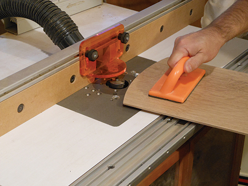
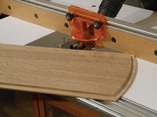
Once all the parts of the side assemblies are ready, you can size the side panels to fit. Trace the curve from the top rail onto the side panel. Use a 1/2″ spacer block to extend the arc to establish a cut line. Now trim and fair the panel curve, before rabbeting the panel to fit. Since the top of the panel is curved, the rabbet is best cut on the router table with a bearing-guided rabbeting bit.
One quick step needs to be taken care of before the side panels can be assembled: cut a 5/8″ deep x 1/2″-wide rabbet on the back legs to receive the back panel. (After inserting the back panel into the rabbets, you’ll attach it with 18-gauge brad nails.) This rabbet needs to be milled before the sides are assembled; otherwise the “L”-shaped front legs will interfere with the cut after assembly.
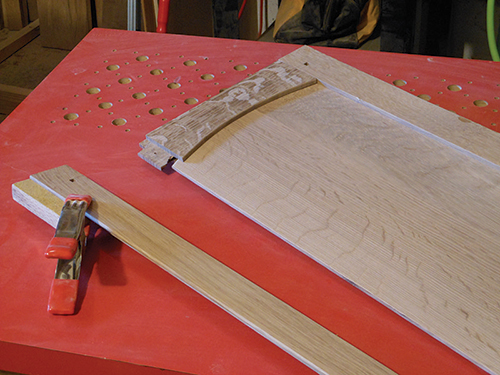
Now test-fit the panels to ensure the curved panel is a good match to the curved top rail. If you choose to crosspeg the joint with square pegs, cut those mortises now. (Alternately, round peg holes can be drilled after assembly.)
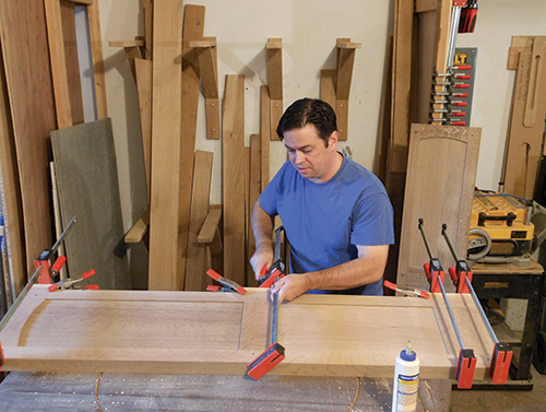
Now, glue and clamp the side assemblies. I sized the panels to allow for at least 1/8″ of seasonal movement. With floating panels such as these, it is helpful to use spacers to center the panel. There are commercially available panel spacers, but I just use self-adhesive foam weatherstripping.
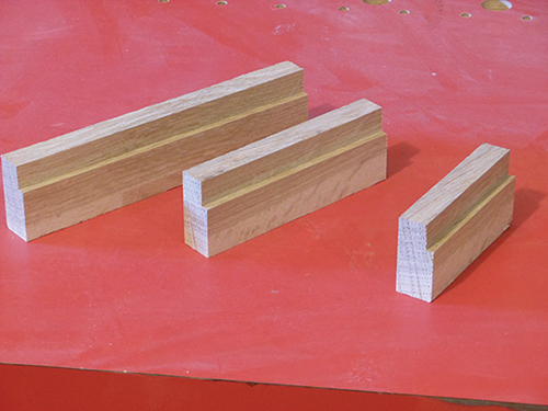
Make up a quick batch of clamping cauls to ride the rabbet on the back legs. Rabbet the caul to mirror the profile of the rear legs, then cut it into three pieces — one for each rail.
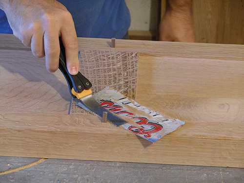
They will prevent damage to the thin lip on the back legs; they also direct straight clamping pressure to properly close the joints.
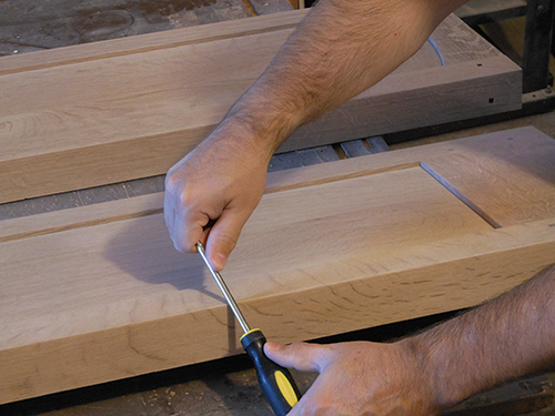
The mortise-and-tenon joints can now be cross-pegged, trimmed flush and sanded. Then burnish the lock miter joints with a smooth-shaft screwdriver. This helps to meld the corner fibers of the joint together, and it’s a step I recommend even if the joints are flawless. Finish-sand the parts with a random-orbit sander, and ease the long edges with a sanding block.
Cutting Dadoes (with a Trick)
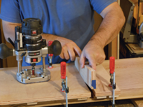
Because the locking miter joints were glued together before the side panels were assembled, you’ll face an interesting challenge at this point in terms of cutting the dadoes. Normally, one could easily mill dadoes in the side assemblies with a router. However, most jigs and straightedge guides won’t work in this application, because the “L”-shaped front legs get in the way.
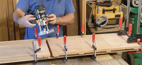
I borrowed an old trick to make an exact-width dado jig that could reliably locate and mill both dadoes on the side assemblies. You simply use two boards with spacer strips underneath as straightedges to cut the dadoes — they also raise the router so it avoids the front leg protrusions. Slide the boards together to gauge the thickness of your shelf stock. Use a scrap of the actual material you will use for the shelf, and butt the straightedges against it so the opening is the same width as the shelf is thick. Clamp the guides in place, and rout the dadoes with a bearing-guided template bit. The bearing follows the guide boards, creating a dado that exactly matches the thickness of the shelf.
A second advantage here to this jig-and-bit setup is that the bearing stops the bit when it contacts the front leg. This prevents you from inadvertently routing too far. To build the full-size jig, cut one piece of 3/4″ plywood to 29-1/8″ x 13″ and another piece to 4″ x 13″. Brad nail strips of 1/2″ plywood to the guide boards to raise them flush with the front legs. Mark the reference edge of the large and the small guide boards, and use the same reference edge on both sides of the bookcase.
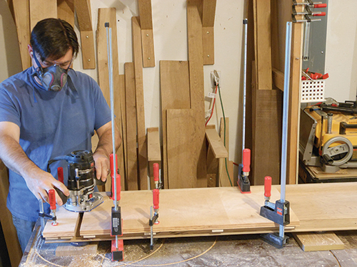
To plow the first dado, position the large guide board flush with the bottom of the side assembly. Then sandwich a scrap of shelf stock between the large and small guide boards. Once the jigs are securely clamped in place, go ahead and rout the upper dado. For the second dado operation, position the small guide board against the bottom of the side assembly. Repeat the shelf-sandwiching procedure, and rout the lower dado.
Make the long top rail for the bookcase next, starting with cutting tenons to fit the mortises in the side assemblies. Then cut and fair the long gentle curve on the top rail, and ease the lower edges with a small roundover bit.
Adding Shelving
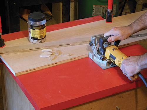
At this point, a dry assembly will help you determine accurate dimensions for the two fixed shelves. Cut the shelf boards to rough size. The lower fixed shelf receives a 2″-wide edging strip, which I attached with biscuits and glue. Plane the hardwood strip to the exact thickness of the lower shelf first, before attaching it.
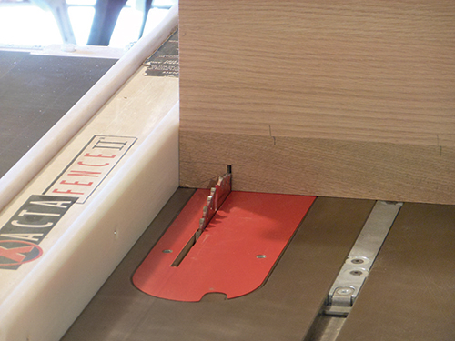
Now that you have the final dimensions of the two fixed shelves, go ahead and trim them to size. Next, notch the lower fixed shelf to fit around the front legs.
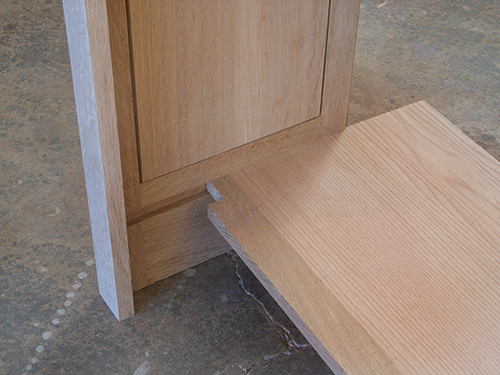
I started these notches with a tall auxiliary fence attached to a miter gauge at the table saw, and finished them at the band saw. Apply glue to the mortises and dadoes, and bring the case sides, two fixed shelves and top rail together.
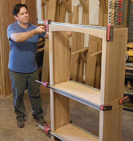
Take note that the upper fixed shelf is not yet edged with hardwood at this stage — it’s our next step. Cut the hardwood edging for the upper fixed shelf to length, and install it with biscuits and glue.
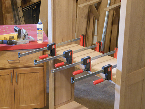
The clamps from the main case assembly can actually flex the shelves slightly and cause measurement inaccuracies. For this reason, remove the long clamps before taking measurements for the hardwood edging.
Building Doors
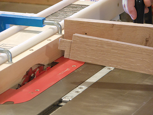
This is the point in case construction that I like best. You have a carcass that is glued together, and you can now move on to more interesting details such as the two doors that grace the lower compartment of the bookcase. I rough-milled the parts for the door frames and stacked and stickered them overnight. I jointed them again the next morning and planed them to final thickness. This two-stage milling sequence takes more time, but I believe it yields straighter workpieces for flat doors.
Rip the rails and stiles to 1-3/4″ wide, and crosscut them to length. Now, with a full-kerf combination blade, mill 1/4″-wide, 1/2″-deep grooves in all the rails and stiles for the door panels. Be sure these grooves are centered. Take the stiles over to the mortiser and deepen the mortises to 1″.
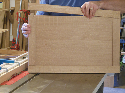
Install a dado blade and sacrificial fence on the table saw next, and cut tenons to fit the mortises. Haunch the tenons to fill the groove, and dry-fit the doors to check your progress. If the corner joints on both doors look good, go ahead and rabbet the back of the panels to fit the door frames. While the corner joints should have a snug fit, I like the solid panels to easily slide into place.
Milling Spade-shaped Inlays
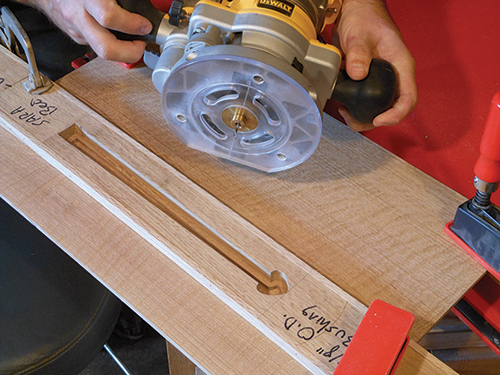
Before permanently assembling the doors, it’s time to make spade-shaped panel inlays. Start by making two templates from 3″-wide x 5/8″-thick hardwood scraps. Use a 1/2″ Forstner bit to drill two holes to establish the curved lobes of the spade shape. I cut the long stem of the template opening with a spiral router bit and edge guide. If you’re not comfortable with that technique, a jigsaw and sanding block may work as well.
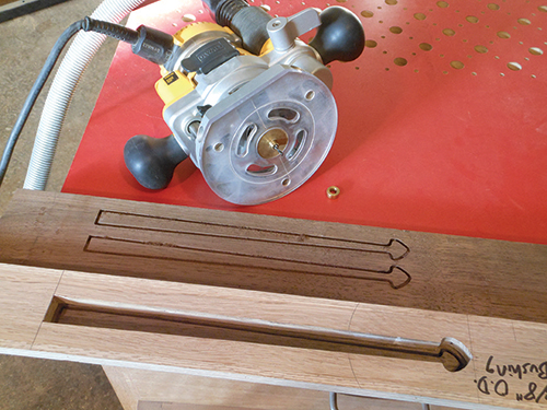
Use a plunge router fitted with an inlay guide bushing kit to excavate each panel recess to 1/8″ deep. With the small brass collar or “wedding ring” installed on the guide bushing, you are ready for the first step in the inlay process.
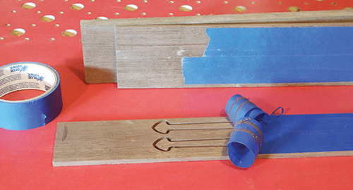
Position the template on the door panel, and clamp it in place. (Bits of carpet tape can further prevent shifting here.) Follow the template around the perimeter in a clockwise direction, and finish by removing the rest of the waste inside the template area.
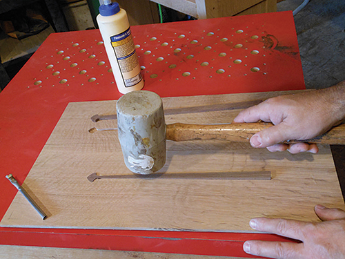
To create the inlays themselves, I chose some nice Peruvian walnut that offers good contrast with the white oak. Remove the “wedding ring” from the guide bushing now, and set the router for a slightly deeper cut than the inlay recesses you’ve made.
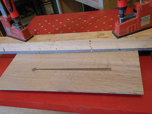
Using the same patterns, carefully mill around the perimeter in a clockwise direction. Keep the guide bushing in contact with the template throughout the cut. I find it helpful to trace the radius of the router sub-base on the template. This helps me anticipate when the router will enter the detailed spade shape. Apply some painter’s tape over the inlay areas to catch them when they are released, and “resaw” the inlays free at the band saw — make them slightly thicker than the depth of the recess. Now lightly chamfer the back edge of the spade inlay with sandpaper to ease the fit. Place the inlay over its recess to check for any gaps. If you are satisfied, go ahead and glue and tap the inlay home.
Drawer Time
At this point, you can measure and construct the hidden drawer. I chose a traditional drawer with half-blind dovetails at the front and through dovetails at the back.
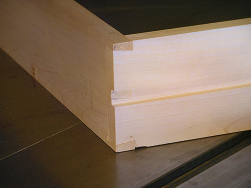
The drawer is side-hung on wooden runners, which require blocking in the lower section of the case. One strip of 3/4″ plywood, stacked with one strip of 1/2″ plywood, will bring the blocking flush with the inside of the drawer opening. Make these but don’t install them yet; they’ll receive a shallow groove to locate the wooden runners.
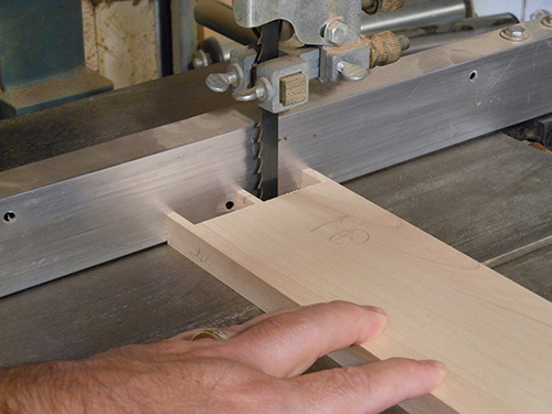
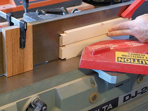
Only a couple of details remain to fit the drawer to its opening. On my rear dovetail layout, I needed to shorten the rear middle pins at the band saw to prevent them from interfering with the wooden runners. Finally, since this is a hidden drawer, the visible gap between the drawer front and the case should be minimal. But, these tight tolerances can cause friction and prevent the drawer from operating smoothly. To solve this issue, I jointed the drawer sides and back slightly narrower than the drawer front to provide some extra clearance. Once that’s done, you are ready to hang the drawer in the case.
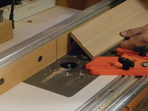
Using the same router table setup and a 1/2″-dia. straight bit, plow a 1/16″-deep, centered groove into both plywood spacer strips and the drawer sides. The grooves in the drawer sides should stop 1-5/8″ from the front edges.
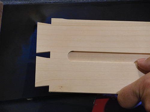
Mill hardwood stock for the drawer runners, sized to slide easily in the grooves, and trim their front ends round. Install the plywood spacer inside the case with glue and brads, and mount the drawer runners in the spacer slots.
Corbels and Other Final Details
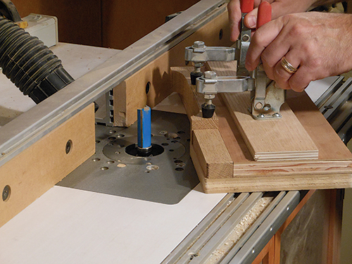
There are six duplicate corbels to make. I used a long router template and bearing-guided pattern bit to shape these, two at a time, on the same piece of stock. Start with 9″-long corbel stock, and once you’ve fashioned the curve on your router jig, use that to trace the corbel shapes. Cut the corbel workpieces slightly outside their layout lines at the band saw. Then clamp them in the routing jig, and rout the corbel stock about halfway along its length. Flip the blank over, reclamp and rout its other end to match. Finally, trim the corbels to finished length, and cut a small chamfer on the bottom edge.
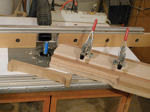
The corbels are attached with biscuits, so #20 biscuit slots need to be cut in the bookshelf and corbels. Use the fence on your biscuit joiner to center these slots. Before installing them, finish-sand the top panel, and ease its edges with a small roundover bit. Temporarily install the top with “figure 8” fasteners and #6 wood screws. Now glue the corbels in place with biscuits, making sure they seat tightly against the top panel.
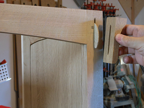
You still need to make four mounting blocks and glue them inside the lower cabinet for the self-closing hinges. Make sure the blocks are glued to the front legs only, and not to the floating panels. Cut the 1/2″-thick plywood back to size and test the fit, then attach a narrow strip of hardwood to its top inside edge for installing figure 8 fasteners here.
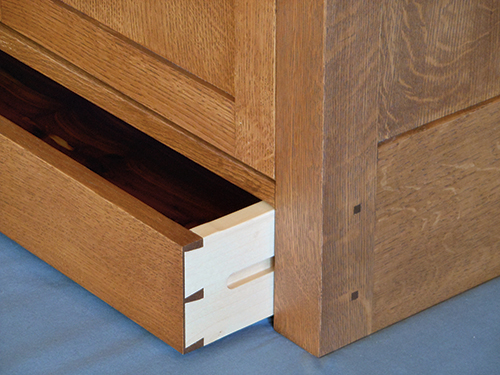
Take a final look over the case with a worklight and complete any final sanding as needed. Then apply the finish of your choice. I used Rodda #19 fruitwood oilbased stain (deep base) and two coats of sprayed lacquer in a satin sheen. I wet-sanded the final coat of lacquer with a 1,500-grit sanding sponge. Working with the grain and using a light hand produced a smooth finish with a subtle glow.
Click Here to download a PDF of the related drawings and Materials List.
– Willie Sandry is a furniture maker and a lumber kiln operator in Camas, Washington.
