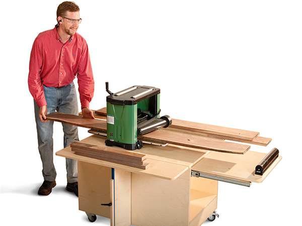
A benchtop thickness planer is an effective and economical way to surface your stock, but very few manufacturers provide a workstand with it — and you definitely need one. A planer should be clamped or bolted securely to a stable surface so it won’t tip when planing long or heavy stock. I’d sure appreciate having convenient surfaces nearby to stack the lumber as I mill it, and wouldn’t it be nice to have a handy form of outfeed support behind the machine when a helper isn’t available? If you’re nodding yes with me, then here’s a project you should build this fall.
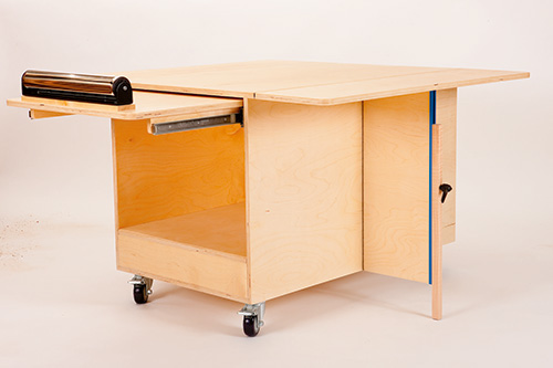
Our planer cart is sized to fit most benchtop planers on the market. It features two tip-up wings on either side that rest on pivoting supports when needed and hinge down flat when you’re done. Finally, a place to park that lumber when processing it! For really heavy loads, we’ve provided drop-down braces on the ends of the supports with locking hardware. Behind the cart, an outfeed table pulls out on full-extension drawer slides. It provides nearly four feet of “helping hand,” with a ball-bearing roller to catch the stock as it exits the machine. No more sprinting around the planer to grab boards at the end of each pass. You can extend the table all the way for really long stock, or retract it some to suit shorter material. A lower shelf will stow even more lumber or other shop sundries, and the cart rolls into position or out of the way on swiveling and locking casters. Pretty cool, huh?
I built the one you see here from the better part of three 5′ x 5′ sheets of Baltic birch plywood. If that isn’t available, two 4′ x 8′ sheets of cabinet-grade plywood will be sufficient, but you’ll have to band the exposed edges of the parts with veneer edge tape.
Assembling the Carcass
Let’s get this cart project rolling by cutting the base and sides to size (pieces 1 and 2). Notice in the Drawings that the bottom edges of the side panels are rabbeted to fit over the long edges of the base. To set up for cutting those rabbets, install a wide dado blade in your saw, and clamp a sacrificial fence to the rip fence so you can bury part of the blade in it. Raise the blade for a 3/8″-deep cut, and adjust the fence so the blade’s cutting width matches the thickness of your project plywood. Make a test cut to check your settings, then mill each rabbet on the side panels. I also used a pair of featherboards clamped to my rip fence to press these workpieces down flat against the saw table — even expensive Baltic birch ply can have bows or twists in it that could make your rabbet cuts inconsistently deep.
Switch from your dadoing setup back to the standard blade so you can cut the three ends, shelf supports and crosspiece (pieces 3 through 5) next. Leave the supports and crosspiece overly long at the moment, but go ahead and crosscut the end pieces to final length. Make sure that their length exactly matches the distance between the sides and base when you hold those three parts in position — there’s no place to hide sloppy butt joinery with gaps here.
Before you can get down to some assembly, load the dado blade back in the saw and set its width carefully for cutting dadoes across the shelf supports to house the crosspiece. Plow them 3/8″ deep and centered on the part lengths.
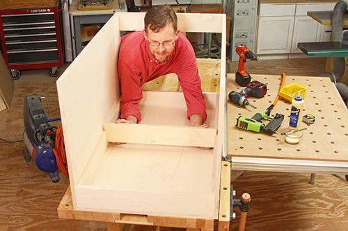
Tote all of your carcass parts over to the workbench for a thorough sanding up to 150- or 180-grit. It’s much easier to smooth these surfaces now while everything still lies flat and open. Once the dust clears, you can fasten the side panels to the base with glue and countersunk wood screws. I first tacked the sides into place with a few brads, then followed behind with screws. Slip two ends into position on the base, and locate the third end piece at the top rear corner of the sides to help the carcass resist racking. Secure these parts with more screws.
The shelf supports come next. Check their length against the actual distance between the installed ends, and trim as needed. Glue and nail them to the side panels. Now install the crosspiece in its dadoes in the shelf supports, cutting it to final length for a snug fit. I brushed a little glue into the dadoes first, slid the crosspiece home and drove brads at an angle and into the supports to pin the crosspiece permanently. Complete the carcass by easing its sharp edges with a 1/8″ roundover bit in your trim router, or use a file or sanding block. Skip the top edges of the sides and the top edges of the end pieces — the top panel and bottom shelf will cover them. Cut and position the top panel (piece 6) so its edges overhang the side panels evenly. Drive countersunk screws down into the cart sides to secure it.
Building the Wing Assemblies
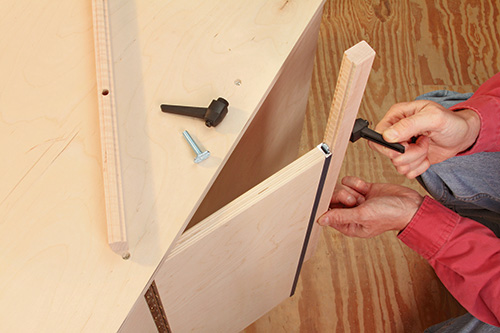
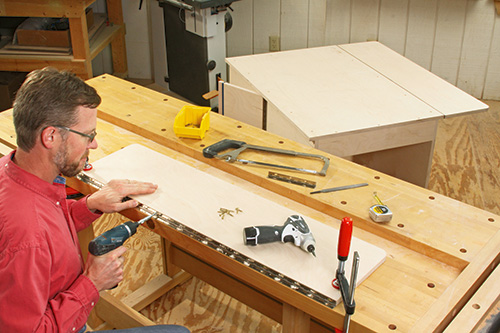
Each of the tip-up wings have wing supports (pieces 7) that pivot out from the cart on continuous hinges (pieces 9). Cut and sand these support panels, and grab a hacksaw to cut lengths of hinges to suit them. I laid out my hinge cuts first to make sure the endmost holes in the hinge leaves were evenly spaced from both ends. Fasten a hinge to one edge of each support, driving short screws into every hole; orient the knuckles of the hinges flush with the face of the plywood.
Notice in the photos that the lever knob hardware holding the extendable braces up or down mounts on the aluminum T-track (pieces 8). Mark two strips of T-track to length. You can cut it quickly and accurately at the miter saw or table saw, but be sure to wear eye protection to protect against metal shavings. Ease the sharp corners of the tracks with a file, then screw them to the other long edges of the supports. You’re ready to mount the supports to the carcass at this point. Just center the supports front to back on the side panels and flush with the top and bottom edges. Screw them in place. You can face the hinge knuckles forward or backward, depending on how you want the supports to fold up; either way works fine, but arrange both supports to fold in the same direction for convenience.
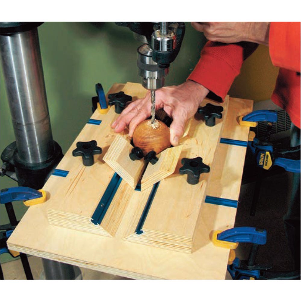
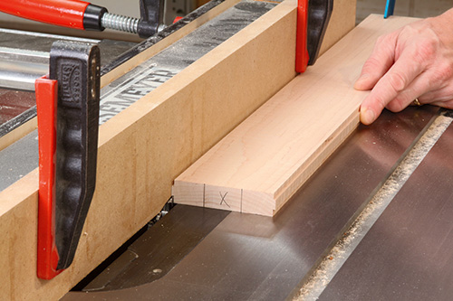
I made both braces (pieces 10) from a wide piece of scrap maple. Use a dado blade to trim a centered tongue along both edges of the workpiece to fit into the T-track channels. These tongues need only be about 1/16″ long — any longer, and the T-bolts won’t tighten properly inside the tracks. Adjust the width of the tongues a tad narrower than necessary so the braces will slide smoothly up and down in the track channels. Rip both braces free and cut them to final length. Now head to the drill press to bore a 5/16″ centered hole through each brace, 7-1/2″ from one end, for the T-bolts. Step to your router table to knock off the long edges and bottom corners of the braces with a 1/8″ roundover bit, and sand them smooth. Install the bolt hardware, and slide the braces into place on the support tracks.
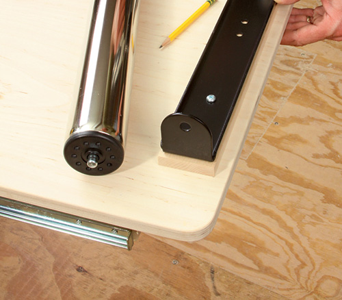
The two wings (pieces 13) start out as square-cornered panels, but I rounded the two outside corners with 1″ radii to make them more “leg friendly” on the final project. Here again, the wings pivot on long hinges (pieces 14), hacksawed to length. I fastened those in place with the wings clamped flat on my bench and the hinges folded open to an “L” shape, with the knuckles facing inward. It kept the hinge hardware flat and aligned, while providing me good backup support when drilling pilot holes and driving all of those little screws! When it comes to hanging the wings, those fancy new pivoting supports and braces won’t help you yet. Fold them out of the way. Instead, you’ll need to ask a helper to hold the wing hinge leaves against the top panel edges while you drive a screw at each end and one in the center. Check to make sure the wings will be flush with the top panel when tipped up. Once these first few screws are driven, you can fasten it the rest of the way on your own.
Adding the Outfeed Support and Casters
Hopefully, your helper is still within earshot to help you flip the project upside down on your bench … I found that to be the easiest way to install the rather heavy full-extension drawer slides (pieces 16). But first, grab a length of rope or a ratcheting tiedown to hold the wings closed before inverting the cart.
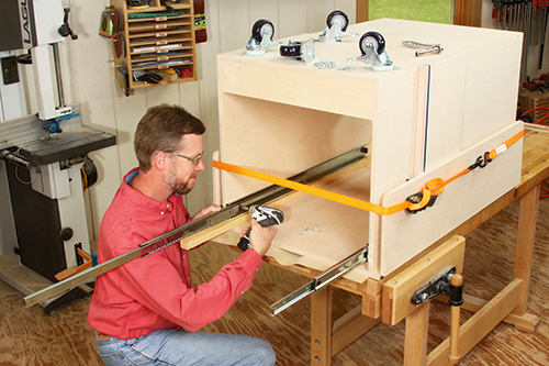
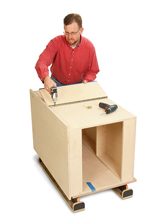
When you study the Drawings, you’ll see that the outfeed table must be positioned low enough to close up inside the cart and accommodate for the height of the roller hardware — the top curve of the roller has to be even with or slightly lower than workpieces exiting your planer. All of this considered, I determined that my slides could be located 1″ down from the top inside face of the cart top. Then, I could shim the roller up as needed to suit my planer’s bed height. So, I used a long 1″-wide spacer to align each slide on the side panels while I drove the attachment screws. Position the ends of the slide housings flush with the back (outfeed) end of the cart when fully closed.
Once the slides are attached and ready to go, install the locking casters (pieces 15) to the cart bottom. I positioned mine 1/2″ in from the outside corners and drove 1/4″ x 3/4″ lag screws with washers to secure them. Flip the cart upright again.
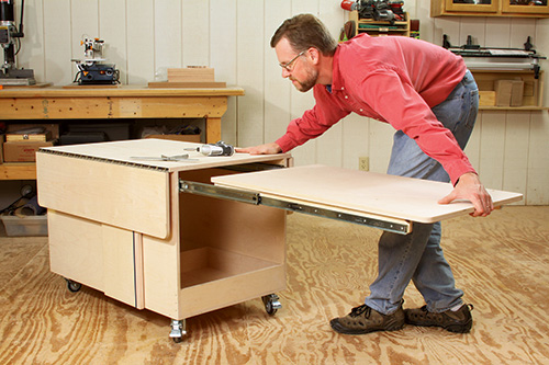
Head back to the table saw to cut the outfeed table and a pair of cleats (pieces 17 and 18) to size. Round the outer corners of the table panel with 1″ radii, and ease its edges as you’ve done previously. Finish-sand these parts before fastening the cleats underneath the table panel so their rear ends are even with its back edge. Space the cleats accurately apart so they’ll align with the slides. Screw the “drawer side” sections of the slides to the cleats. Adjust the front ends of these parts flush.
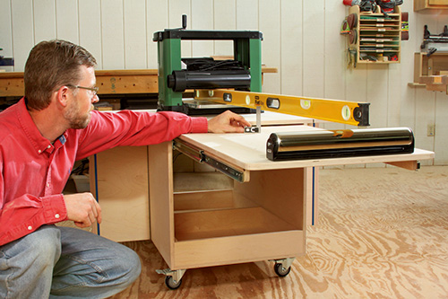
Once your outfeed table is installed, pull it out all the way, and position the roller (piece 19) near its end. Set your planer on the cart, and shift it so its infeed table, when lowered for use, is about even with the front (infeed) end of the project. Now use a long level, resting on the planer bed, to help measure the height between the planer bed and outfeed table surface. Subtract the height of the roller, and you’ll know the thickness you need to make the shim (piece 20) that will bring the roller up to final alignment. Make the shim and screw it to the outfeed table, 1/2″ from the end. Fasten the roller housing to it, and clip in the roller. Verify that the height is correct using the level again. Workpieces should lightly graze the top of the roller as they leave the planer. Adjust the shim thickness now, if needed.
The Final Details
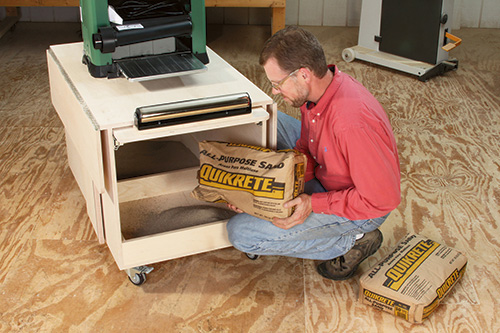
Given the locking casters, an overall low stance and the weight of the plywood, this cart is very stable already. But since I anticipate needing to plane really thick and long stock now and again, I added 50 lbs. of mortar sand to the base. With this ballast, I may not even need to lock the casters for typical jobs. Then I cut the bottom shelf (piece 21) to size, sanded it and screwed it to the shelf supports and crosspiece.
Fill all the screw counterbores with wood plugs, and chisel them flush. The last step that stands between you and many hours of convenient planing to come is to finish your cart. Instead of removing all of the hardware, I simply masked off the metal parts and casters, and I sprayed on four coats of satin aerosol lacquer. It’s easy to apply, sufficiently durable and dries fast as lightning. I was all done spraying and the finish was dry in about two hours’ time. Finally, drill holes for the bolts you’ll need to secure your planer to the “deck.” I used carriage bolts, which allowed enough clearance for the outfeed table beneath. I fastened them with washers and nylon-insert lock nuts from above. Here’s a project that’s already getting a workout from me each time I process new lumber. I’m sure your cart will, too!
Click Here to Download the Drawings and Materials List.
Hard to Find Hardware
Universal T-tracks (2) #27179
Piano Hinges (2) #33305
Ratchet Lever Knobs (2) #90910
T-bolts (2) #83311
3″ Swivel Locking Plate Casters (2pr) #38865
Roller Assembly (1) #20829