We’ve all been through it…upside down, behind the TV, trying to make sense out of an impossible matrix of wires, cables, power strips and so forth, the flat-screen TV precariously balancing on the cabinet, rocking dangerously to and fro as you plug and replug wires in the hopes of getting both sound and picture from your new system. It seemed like a problem that we would all just have to bear — like crabgrass and taxes. Then editor Rob Johnstone had this idea of making a cabinet that would pull out on enormous slides, bearing the weight of the TV and all the electronic components, making it much easier to get behind the gear and hook up the cable to the DVD or Blu-ray with surround sound and the Playstation to the — well, you get the idea.
Designing a substantial piece of furniture with moving parts capable of bearing around 500-lb. loads without tipping over and landing on an innocent party became the goal. Jeff Jacobson and Larry Stoiaken noodled through several ideas, after which Jeff came through with CAD drawings. That’s when I got busy and put together a full-size mock-up in MDF — always a good idea when working through a new design. In this case we especially needed to try out the moving parts and determine how best to anchor the cabinet to the wall or floor. (Actually a good idea with any large or tippy cabinet with a 60″ TV, even if it does not have a slide-out section!)
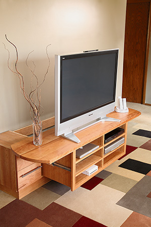
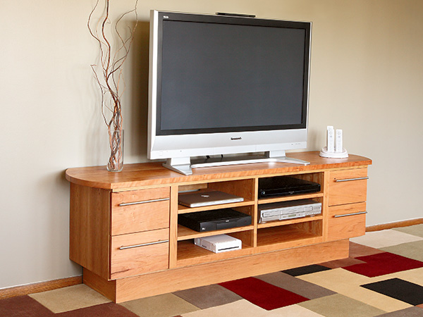
At the end of the process, we settled on the configuration you see above, where the entire top glided out with the center console, creating a large, stable surface that presented an unbroken visual line at the top of the cabinet. The center console needed to be large enough to contain most, if not all, sizes of electronic media components, and obviously strong enough to handle the weight of everything. We chose two Accuride glides rated for 500 pounds for the sides of the console and two Accuride 250-pound glides beneath it. These provide around 1,500 pounds of load-bearing strength, allowing us to support not just the TV monitor and components but perhaps even a safe and a boat motor … just in case!
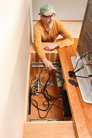
The key to this whole design is access, so we decided not to put a back on any of the casework to help move that goal forward. We also chose a large, double-barrel grommet to fit through the top behind the TV, for cable and wire access. Once we figured all that out, and picked out the drawer glides, pulls and adjustable feet, material selection was a piece of cake!
SAFETY NOTICE!
This cabinet must be attached to the wall and the TV must be secured to the top of the cabinet. Use the locking pin to avoid accidental roll-out.
Kicking It Off
Developing a cutting list was easy, too: we simply took measurements from our mock-up, another benefit of a prototype approach to woodworking design.
There are several major parts to this project. The plinth, or base, holds everything off the ground. The two side drawer cabinets share a common base panel that covers the plinth and becomes an attaching point for the bottom glides on the center console. The center console is attached to a sub-top that’s flush with the casework beneath it, and this in turn is attached to the solid cherry top which overhangs the casework by 2-1/2″ at the ends and 5/8″ at the front.
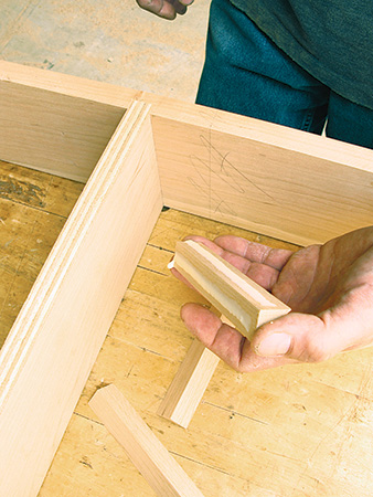
I started with the easy stuff. I built the plinth using solid cherry for the front and sides for durability on these high traffic parts and cherry veneered plywood for the back and middle parts. You can find all the dimensions for these pieces in the Material List on the facing page.
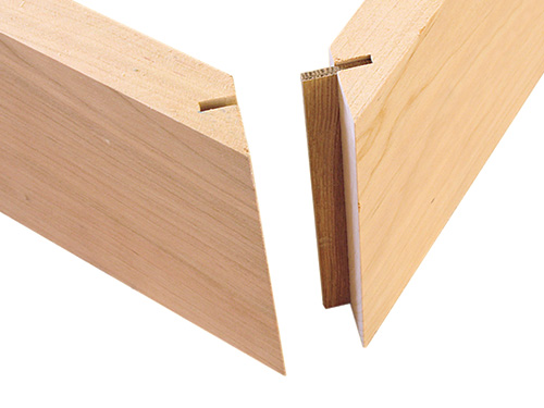
I decided to spline the mitered front corners and plowed dadoes for the cross members, then used a fun little trick called glue blocks to reinforce all the corners. As woodworkers through the ages can attest, glue blocks deliver amazing strength with just a small amount of effort and material. I glued and clamped the plinth together and then allowed the glue to cure.
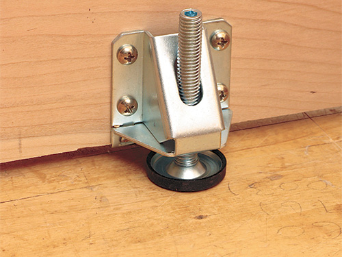
Once everything was set, I mounted six heavy-duty lifting levelers to the front and back — it is important to have the ability to level a big piece of casework like this — without using old carpenter’s shims in your living room!
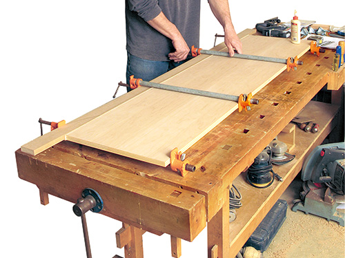
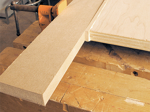
Before I went any further with the casework, I decided to glue up the top. It is a bit out of sequence, but I could come back to it as I waited for other clamped and glued subassemblies to cure. The top is a simple, butt-glued panel. After I jointed and planed the stock, I examined the grain patterns and composed the pieces. I glued the top together and then set it aside for future attention, once I had built everything else.
Cabinet Parts
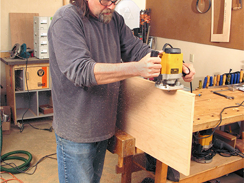
The plywood components for the drawer cabinets were next on the agenda. I put a sharp saw blade paired with a zero-clearance insert in the table saw and started ripping and crosscutting pieces — again, look to the Material List for their sizes. All the panels’ exposed edges got banding of 1/4″ solid cherry before final sizing and spline cutting. The joinery for all these carcass parts was butt joints and biscuits. Take your time to lay out the biscuit locations carefully, and you will save yourself a lot of misery.
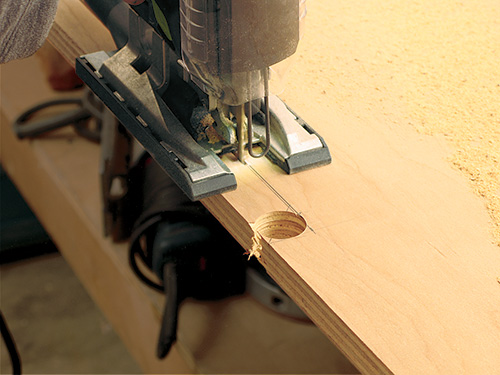
In addition to the biscuit locations, there is a long notch cut out on the back edge of the carcass bottom. The notch is there to allow power cords and other sorts of wiring access to the center sliding console. Look to the Elevation Drawing for the location of the notch. I used a Forstner bit at either end of the notch and then cut the rest of it away with a jigsaw.
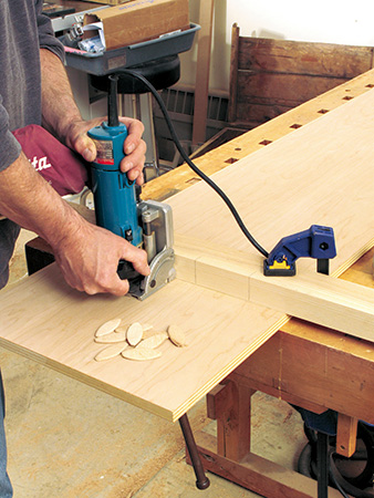
One of the most important pieces on this cabinet is the carcass rear stringer that runs the whole length of this subassembly. It sits in notches on the vertical dividers and is biscuited into each carcass end.
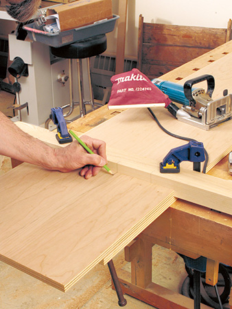
This stringer is the means by which you attach this cabinet to the wall, which you must do to safely operate the sliding console. If you don’t attach it to the wall, the whole cabinet will tip over and your expensive equipment will end up in a landfill somewhere.
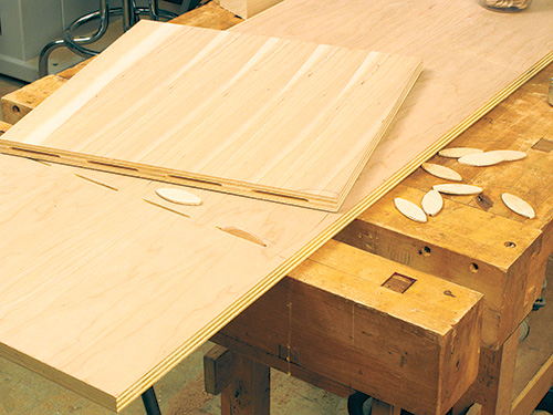
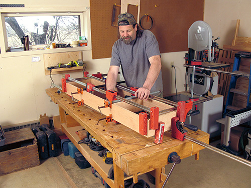
With all the machining done for the carcass, I performed a final test fit. Everything was jake, so I took the time to sand all the pieces before final assembly. I clamped the subassembly together and set it aside while I went on to build the center console. (Do you see a pattern here?) Although it could go without saying, I am not going to risk it: make every effort to be certain you have clamped up the carcass square and true. Remember, you can’t reverse a glue-up step.
The Electrified Slide
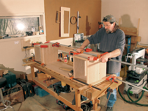
The sliding center console is the heart of this project’s design. Even so, it is pretty much bread-and-butter casework construction, just as you did with the carcass. Once again, the cherry veneered plywood pieces have solid cherry lipping on their exposed edges. The exception for that is the face frame area. The center console needed to allow for the thickness of the heavy-duty slides (they are so robustly made that they are 3/4″ thick compared to the standard slide thickness of 1/2″!), so Jeff designed a face frame to fit into the center of the case to hide that unsightly hardware. It sits in the same plane as the drawer faces, which overlay the casework behind them. He also added a center vertical divider for additional strength, allowing us to eliminate any fixed shelving and giving you even more options in loading up the electronic stuff into your “ultimate” media cabinet.
I biscuit-joined, sanded and assembled the console in the same manner as the carcass, with the additional step of drilling shelf-pin holes. See the Drawings for the locations of the holes. Like the other plywood pieces, the shelving is simply edge-banded and sanded smooth. The limited size of these shelves means they won’t sag over time; otherwise I’d have suggested solid wood shelving.
As I mentioned before, the glue stage step is irreversible, so the dry-fit pre-assembly step cannot be done too carefully. Take your time, apply the clamps as you would if you were using glue, and then test for square. When everything fits perfectly, go ahead and do the glue-up.
When the glue has cured, set this subassembly aside, too. (You will be getting a pretty big pile of “set asides” by now!)
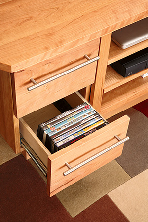
At this point, I went back to work on the carcass subassembly, building and fitting the drawers using the Accuride drawer slides. In this instance, the drawer construction was simple: 1/2″ Baltic plywood rabbeted at the corners. I glued the joints and drove trim nails into the corners. The bottoms were 1/4″ Baltic plywood panels captured fully within a dadoed housing. Look to the Drawings for the details of these simple drawers. One detail you will notice is that the sides of the drawers are shallow, which allows for easy finger access when grabbing your favorite movie or game cartridge.
The drawer faces are made from solid cherry lumber and are attached with screws driven from the inside of the drawer boxes. Getting these faces to line up with each other and the face frame of the center console proved to be the most challenging woodworking task of the entire project, in my opinion. I’m great at making hand-cut dovetailed and hand planed fitted drawers — it’s the easy stuff I sometimes struggle with. Be patient and as accurate as you can. Fortunately, with a 1/8″ reveal you have some room for trimming and fitting. I was grateful for that reveal, I can tell you.
Demanding Drawer Slides
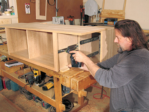
I installed all the of the slide hardware basically by the numbers, meaning I use the manufacturer’s specs and make my measurements precise. The drawer slides on the drawers (as opposed to the console) fully disengage, and I was able to mount each slide part to its mating surface on the drawer and cabinet sides. I simply measured, taking into account all offsets, then precisely marked and screwed them in place. For the aluminum drawer handles, I made a template out of scrap 1/4″ birch plywood, clamped it to the drawer face with a backer block and drilled straight through for the mounting screws. Easy breezy…
That was the drawers…the center console, however, has the Accuride super heavy-duty slides that do not come apart into two pieces, which made things a bit more complicated. After noodling over the challenge, I started out by setting the bottom slides (which are detachable) to the carcass bottom and the adjoining bottom of the center console — again, doing it by the numbers to manufacturer’s specs: all of the required offsets, etc., which are basically built into the casework. I attached the big glides to the vertical dividers of the carcass and then blocked and shimmed up the center console to connect with the carcass at just the right spot. I connected the smaller glides, pushed the center in a little ways and checked my marks against the screw holes on the slides (wow, good job!) and fastened it down. Then it was time to test it out: I can’t begin to tell you how nice it worked, better than the drawers. I even impressed myself on this little step of the job; it was far easier than I anticipated.
Driving It Home
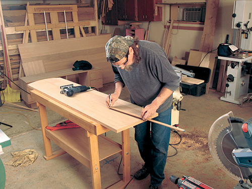
It was now time to start thinking about finishing this project off. Remember the top that has been waiting patiently on the sidelines? There was some work left to do on it. I first hand planed it with a #07 beater plane of Rob’s, then started at about 80-grit with a Festool 6″ random orbital (sorry, purists … you’ll notice the drawers are pinned also). I cut and shaped the top before the final sanding, then gave it a coat of Watco® before setting it aside again to start getting the casework prepped and ready for finishing. I needed to work on the reveals some more, getting all the lines looking straight. I eased all the edges along with a final clean-up scuff sanding using 220-grit paper before tacking and rubbing in a coat of Watco. A penetrating oil finish on cherry brings out the grain like no other treatment, in my opinion. Even if you are going to apply a durable topcoat like polyurethane, I would still recommend taking the time to apply a coal of oil before the poly.
After an overnight dry, I mated the top to the sub-top of the center console, simply screwed in place but with elongated holes at the front and middle to allow for movement of the cherry top.
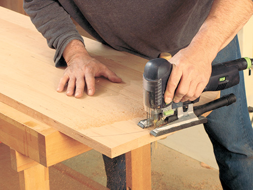
Next I drilled holes for the grommet hardware through the top and the subtop. I confess to a bit of anxiety; I was using a really big bit on a really nice top! After the holes were drilled, I used a jigsaw to connect the holes for the grommet. Following that, I drilled the 3/8″ hole for the locking pin. This dowel keeps young children from “accidentally” pulling the console forward unsupervised.
I then gave it all a light rubdown with #0000 steel wool, tacked the surfaces clean and applied another coat of Watco Danish oil.
This was a very fun, very cool project to work on. I don’t think it’s a groundbreaking achievement in the world of fine woodworking, but it sure offered up a number of challenging elements to bang my head against, some beautiful wood to use and cool moving parts! Imagine the ease with which you’ll reconnect your Xbox or new amplifier, Blu-ray or an “old style” DVD player to your system, with no chiropractor bills for your efforts or shorted-out components!
Click Here to Download the Drawings and Materials Lists.
Hard to Find Hardware
Heavy-duty Drawer Slides (1 pr.) #31416
Accuride Drawer Slides (5 pr.) #32482
Drawer Pulls (4) #23331
Heavy-duty Levelers (2 packs) #81239
Hex Wrench for Levelers (1) #81253
Black 1/4” Pin Support (1) #22781
