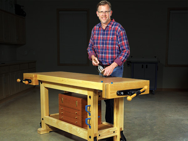
Today’s trendy Roubo workbenches can require a bank loan to afford and feature some complex details that are challenging to make for the average woodworker. These modern “wonder benches” are up to task, without a doubt! But they don’t have to be the be-all and end-all of bench designs. Stout and heavy with a flat top is what you want. Fancy and expensive, however, need not be part of that equation.
Twenty-plus years ago, my first attempt at a “workbench” was a modest affair. It was an oversized table I made from 2x lumber and a doubled-up layer of 3/4″ MDF for the top It took a beating for a lot of years and helped me build many projects until I finally retired it. I traded up — or so I thought — for an expensive prefab bench that has never really been heavy enough not to skitter along the floor when I’m hand-planing or wrestling large assemblies on it. And it’s had a wide tool tray down the middle that I would gladly have traded for a more flat benchtop instead. So I’ve been musing about building a workbench that had more heft and a better top.
Making the Legs
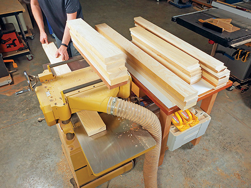
Prepare enough 3/4″- and 1-1/2″-thick stock for the first six parts of the Material. (If you can’t get thick lumber, you could laminate what you need from 3/4″ stock for the centers of the legs and stretchers.) Even though we’ll start by making the legs, you’ll gain efficiency in the surfacing process by including stock for the long stretchers now, too.
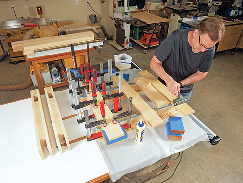
Rip and crosscut blanks for the inner and outer leg workpieces. Leave them about 1/8″ overly wide for now. Make up four leg blocking pieces, too. Arrange the dimensions of the leg blocking so their long grain follows the 3-3/4″ dimension; that way it will align with the long grain of the other leg parts.
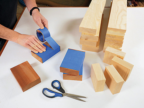
The tops of the legs and the long top stretchers connect in bridle joints at the top corners of the bench’s base assembly. In a similar way, the long bottom stretchers engage the legs in mortise-and-tenon joints, where the inner portion of these stretchers form a tenon that fits between the leg blocking and the inner leg laminations. To keep the center opening of the bridle joints and the mortises consistent when assembling the legs, make up a pair of 4″-wide x 6″-long spacers from scrap 1-1/2″-thick stock. Surface these spacers 1/32″ or so thinner than the inner leg and stretcher laminations, and wrap their bench made by hand-tool guru Rob Cosman. His design, faces and edges with wide strips of painter’s or packing tape to prevent glue from sticking to them. Then glue and clamp two outer legs, an inner leg and a blocking piece together with these spacers installed to create the first leg. When the clamps are in place, give the leg an hour or so for the glue to set before sliding the spacers out of their openings so you can reuse them to glue and clamp each of the other three legs together. When the spacers come out, carefully clean away any glue squeeze-out from these openings before the glue hardens.
Flatten one laminated edge of each leg on your jointer, and run the legs through your planer to flatten the other edge and reduce them to a final width of 4″.
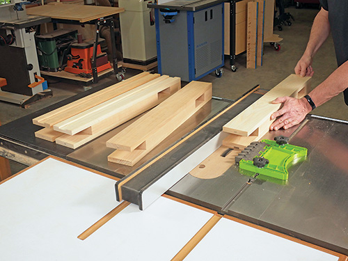
Mark the bench’s four legs for the orientation you want them to be in when the framework is fully assembled. Notice in the Exploded View Drawing on the next page that the bench’s short stretchers (pieces 8) fit into grooves on the inner faces of the legs. These grooves will prevent the short stretchers from twisting out of alignment in the base over time. Cut these 1/4″-deep, 1-1/2″-wide grooves in the legs with a 7/8″-wide dado blade installed in your table saw. Set up for the groove cuts by raising the blade to 1/4″ and positioning the rip fence 1-1/4″ away from the closest face of the blade. Plow each groove into the leg in two passes, flipping the leg end for end between passes. This way, the grooves will be automatically centered on the inner leg faces.
Creating the Stretchers
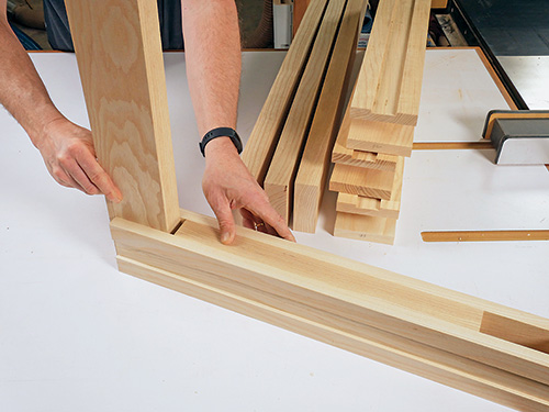
Before fabricating the upper and lower long stretchers, make sure the thickness of the inner lamination pieces allows them to slide easily into the bridle joints and mortises of the legs. If they don’t, plane the inner stretchers slightly thinner to create a “slip fit” into the legs that doesn’t require pounding in.
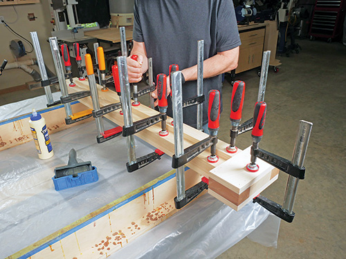
Rip the four inner and six outer stretchers about 1/8″ overly wide, and crosscut them to length. Rip and crosscut the pair of narrower shelf supports to final size. Then glue and clamp an inner long stretcher between two outer stretchers to create each long upper stretcher. Make sure the tenons on the ends of these components are 4″ long and their shoulders (formed by the outer stretcher laminations) are even with one another. I used a simple scrap-made jig, which wraps around the inner lamination, to guarantee that the shoulders would align.
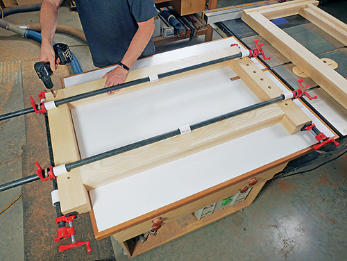
Assemble the long lower stretchers by gluing and clamping an outer stretcher, inner stretcher and shelf support together. Here again, the inner stretchers form 4″-long tenons on the ends of these components. Position the shelf supports so their bottom edges are flush with the bottom edges of the outer and inner stretcher laminations.
Assembling the Base
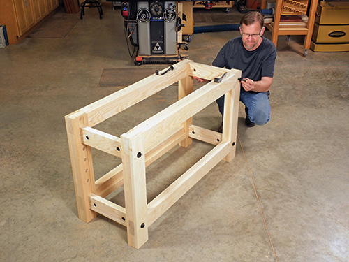
Consider drilling a series of 3/4″-diameter holes into the front face of the front leg opposite the one that’s nearest to the side vise (it’s the right front leg in the Exploded View drawing). These holes can be useful for inserting pegs to help hold up workpieces that are being clamped on-edge in the side vise, for hand-planing edges. Four or five, spaced about 3″ apart, should be sufficient. Bore them on a drill press with a 3/4″-diameter Forstner bit. I drilled mine all the way through the leg so they can stow my collection of hold-downs when I’m not using them. I chamfered the rims of these holes to minimize the chances of them splintering during use.
We’ll attach the legs and short side stretchers with Rockler’s heavy-duty 1/2″ cross-dowel bolts and cross dowels. These bolts also will lock the bridle joints together on one end of the bench as well as secure all four of the mortise-and-tenon joints of the lower stretchers. Mark the cross-dowel bolt locations carefully on the legs, making sure they are exactly centered on the widths of the legs. Locate them 5-3/4″ up from the bottoms of the legs and 2″ down on the legs that will be on the opposite end of the bench from the tail vise (on my bench, these are the left front and back legs). The short upper stretcher closest to the tail vise, however, will need to be positioned 2-1/2″ down from the tops of these legs to allow clearance for the tail vise hardware. So, mark center points for those cross-dowel bolts 4-1/2″ down from the tops of the legs. Drill the cross-dowel bolt holes through the legs.
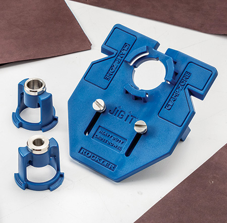
Next, rip and crosscut the four short stretchers from 1-1/2″-thick stock, and drill them for both the 7/8″-diameter cross dowels and their 1/2″-diameter bolts. Locate the center points of the cross-dowel holes 2-1/4″ in from the part ends.
Dry-assemble the long top and bottom front stretchers and front legs, and clamp this assembly together to close the bridle and mortise-and-tenon joints tightly. Extend the cross-dowel bolt holes through the stretcher tenons of all four joints with a 1/2″ brad-point or twist drill bit, using the bolt holes in the legs as guides. Repeat this process for drilling bolt holes in the long top and bottom back stretchers and back legs.
Now drill four holes through each long top stretcher at your drill press for lag screws that will eventually attach the base to the benchtop. Make sure the hole diameter is large enough to allow clearance for the shanks of the lag screws you’ll be using to slide through (my lag screws are 3/8″ in diameter, so the holes were slightly larger). I then counterbored these holes on what will become the bottom faces of the stretchers in order to recess the lag screw heads by 1/2″.
Take some time to sand the legs and long and short stretchers smooth while their faces and edges are still fully accessible. It’s easier to do this now than after assembly. Ease the long edges of the legs and stretchers with roundovers or chamfers to minimize splinters. The top edges of the long top stretchers can remain square, since they’ll butt against the bottom face of the benchtop.
Because the upper short stretcher closest to the tail vise is set down from the tops of the legs to clear the vise hardware, the cross-dowel bolts that secure this stretcher don’t intersect and lock together the bridle joints of the long stretchers above them, as they do on the other end of the bench. Instead, we’ll pin these two bridle joints together with glue and 3/4″ dowels driven into them from the inside faces of the legs. So, dry-assemble the front and back leg/ stretcher assemblies again but spread glue onto the contact surfaces of the two “tail vise” bridle joints. Clamp the assemblies and check their diagonals for square. Now drill a pair of 3/4″ holes 2-1/2″ deep through the glued bridle joints for dowels. Cut two hardwood dowels for each joint, spread glue inside the holes and drive the dowels home with a mallet.
Bring the front and back frame subassemblies together by installing the short stretchers between them. Insert the cross dowels and bolts into their holes, thread them together to engage the hardware and tighten the framework securely.
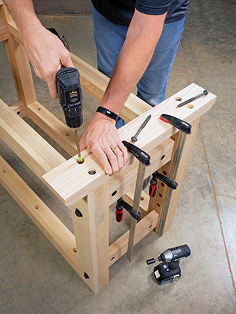
Let’s finish up some details on the leg bottoms. Rip and crosscut a pair of leg bases to size, and head to the table saw to nibble their top outer corners off at 45 degrees — they’ll be less of a nuisance for your feet this way when standing close to the bench. Invert the workbench base framework so you can attach the leg bases to the bottoms of the legs with pairs of 3″ countersunk lag screws driven through the bases and into the center laminations of the legs.
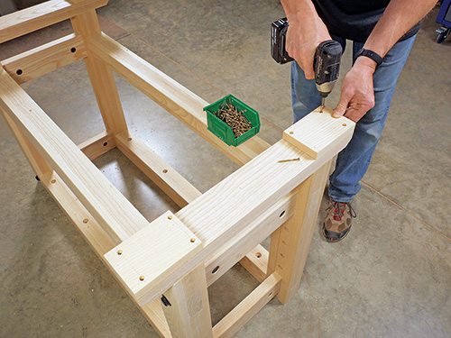
Now prepare a couple of feet for each base from 3/4″ hardwood stock. Attach the feet to the bottoms of the leg bases, flush with their ends, using glue and 1-1/2″ countersunk screws. Ease the bottom ends and edges of the feet with a 1/4″ roundover bit to prevent them from chipping when the bench is dragged around the shop floor.
Laminating the Top
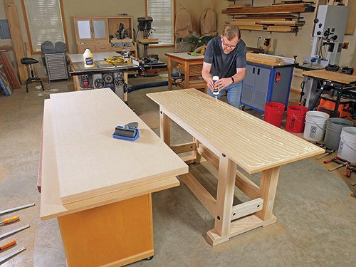
The 3″-thick core of this bench’s top consists of four laminations of 3/4″ MDF. You’ll need two 4×8 sheets to create the top blank. If you haven’t worked with MDF before, it’s dense and heavy but easy to cut, rout and glue together. The challenge to laminating this top, however, is keeping the ends and edges of the MDF sheets aligned while the glue is acting as a lubricant and you’re tightening the clamps. Here’s the solution to that conundrum. We’ll laminate the top in stages and progressively flush-trim each layer to final size before installing the next layer. That way, the laminations will align perfectly in the end, regardless of whether a little misalignment occurs during each stage of the glue-up process.
Begin by cutting a piece of MDF carefully to 23-1/2″ x 71-1/4″. Cut the second layer 1/4″ oversized in both dimensions. Roll a thin layer of glue over one face of the larger (second) panel, set the smaller panel on top of it and adjust the sheets for an even overhang. Weigh the top layer down with heavy bags of sand, concrete blocks or five-gallon buckets of water (I used ten full buckets). Install clamps around the perimeter of the sheets to squeeze the glue seam tightly together all the way to the panels’ edges.
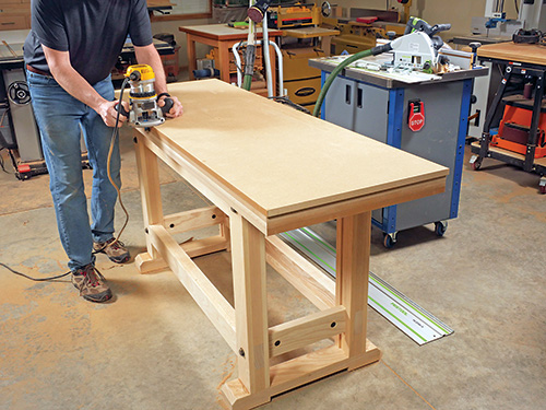
When the glue fully tacks up — give it a good hour or so — flip the sheets over on a raised work surface, and flushtrim the edges of the larger sheet with a handheld router and piloted flush-trim bit. The bit’s bearing should ride along the smaller sheet for this cut. Once routed, both sheets will be dimensionally identical. Repeat this process two more times, applying the next overly large lamination, then flush-trimming it to match the edges of the stacked core.
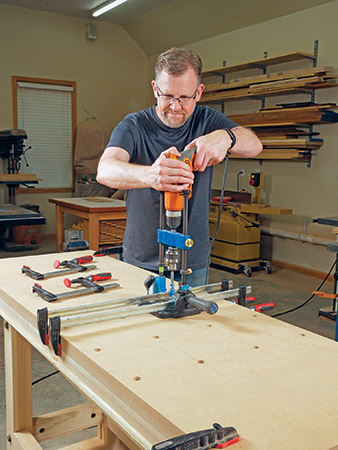
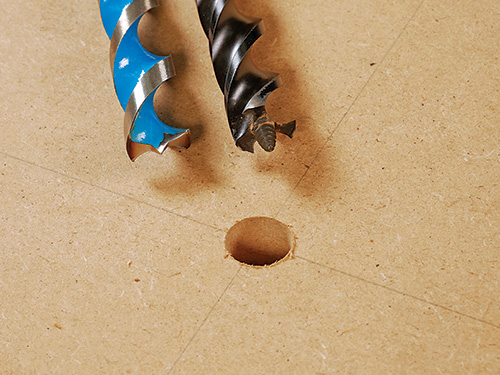
Next up, it’s time to lay out and drill a grid of 3/4″-diameter bench dog holes through the top. Where you place them is up to you. (A PDF diagram of my bench’s hole placement is available here.) Here’s a case where you’ll want to drill squarely through the thickness of the top, so install your handheld drill in a portable drilling guide. I used a 6-1/2″-long auger bit with a brad-point tip on it for boring these holes. A typical auger bit with a threaded tip won’t work well in this application, because the bit’s screw threads will plug up with MDF fibers, and then it won’t self-feed and stops cutting. But brad-point auger bits are often available at home centers, or you can find them online. Alternately, you could also opt for a long Forstner or twist bit. When all the holes were drilled, I chamfered their rims with a router to tidy them up.
Rip and crosscut the front, back and side edging strips for the benchtop from 3/4″-thick hardwood. The purpose of this edging is to cover and protect the more fragile edges of the MDF core as well as hide them. Arrange the edging for your bench’s top to suit whether you’ll install the shorter side vise on the front left or right corner. (Right-handed users should locate this vise on the left corner, as I did on my bench. Lefties would locate this vise on the front right corner instead.) Then round over the outside corner of the side edging strip that will form the outside back corner of the benchtop, opposite from the side vise. I did this with a 1/4″ roundover bit in a compact router.
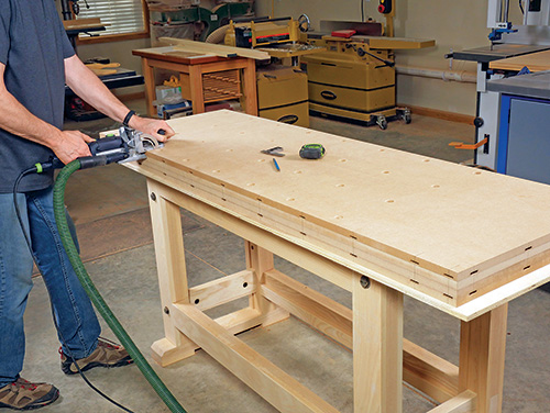
The edging strips should be attached to the benchtop core with a mechanical connection, such as biscuits, splines, Dominoes, nails or screws. Glue alone won’t offer enough shear strength for a sturdy connection. I used size 6 x 40 mm Dominoes and glue to install the edging on my bench, insetting the Dominoes 1/2″ in from the top and bottom faces of the core and spacing them about 71⁄2″ inches apart in pairs.
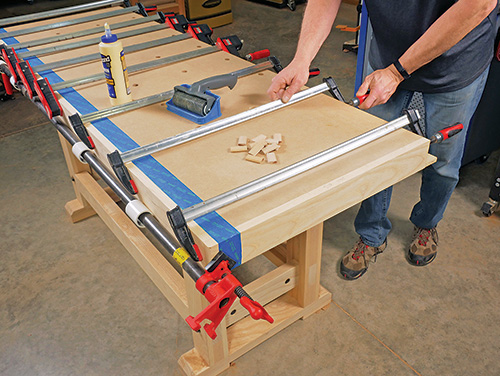
When you unclamp this glue-up, plane, scrape or flush-trim the top and bottom edges of the edging, if needed, to bring them flush with the benchtop faces. Then ease the top and bottom corners of the edging with a 1/4″ roundover bit, or chamfer them, to prevent splinters. At this point, I applied two coats of water-based polyurethane to the bottom face of the benchtop to seal the MDF.
Installing the Vises
To prepare for installing the bench’s tail and side vises, make up two pairs of wooden vise faces for each from 1-1/2″ or 1-3/4″-thick solid stock — it’s okay to laminate thinner stock together to make up these thick faces. For my tail vise, I had enough 8/4 ash lumber on hand to make the tail vise faces from single pieces. For the smaller side vise, however, I glued up 4/4 boards to create blanks for the vice faces instead. Rip and crosscut the four vise faces to final size.
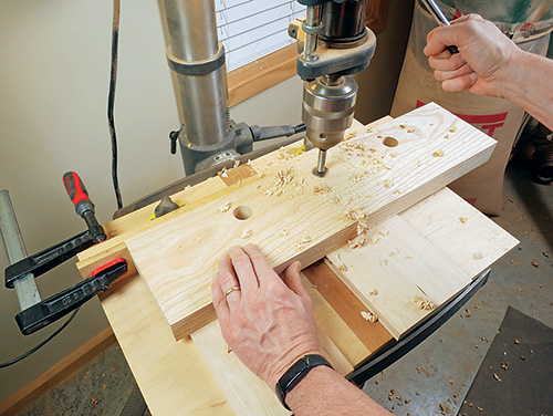
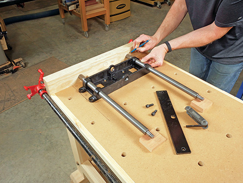
Let’s install the tail vise first. Set one of the two wooden faces against the end of the bench and clamp it in place. Now unbolt and remove the vise’s guide rods and screw/end plate assembly from the cast-iron base piece. Then set the vise’s base against the back of the wooden vise face and center it carefully, widthwise, on the bottom face of the benchtop. Slide the steel rods back into the base in the opposite direction so their flat ends can make contact with the vise face, rather than the threaded ends. Trace around each of them on the back of the vise face to mark the exact position of the three holes (two for the guide rods, one for the vise screw) you need to drill through the vise face. Drill three 1-1/8″-diameter holes through both vise face workpieces at the marked locations. Do this at a drill press, using a stop block clamped to a fence to register the positions of the holes so their placement matches on both vise faces.
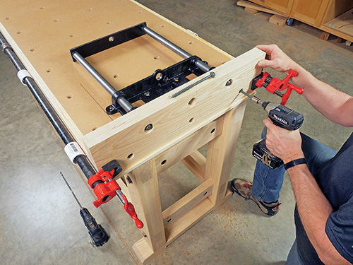
Now fasten the inner vise face to the end of the benchtop; I used four 5″ lag screws driven into pilot holes with 1/2″-deep counterbores to recess their hex heads.
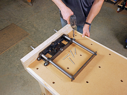
If you haven’t done so already, reinstall the guide rods and end plate assembly on the vise’s cast-iron base, and set the base into position on the benchtop, extending the guide rods through the holes in the vise face. Mark center points for each of the base’s mounting holes, drill pilot holes and fasten the base to the benchtop with #12 or even #14 x 2-1/2″ wood screws, if you can find them. Instead of screws, I decided to use washerhead lag bolts with deep threads, for maximum strength.
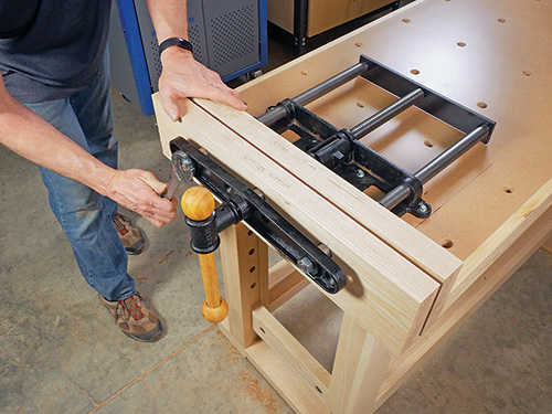
At this point, I cut large chamfers on the corners of the outer vise face for each vise at my table saw. Slide the outer wood vise face onto the guide rods, and replace the vise’s screw assembly and cast-iron outer plate, attaching them to the guide rods with nuts. Wrap up the installation by securing the outer wood face to the vise’s outer cast-iron plate. I used #14 x 1-3/4″ wood screws here.
Repeat this whole process for installing the side vise on the front edge of the benchtop. For this vise’s smaller hardware, you’ll switch to 7/8″-diameter holes for the vise screw and guide rods instead. I used washerhead lag screws again to mount the vise’s base and #14 x 1-1/2″ wood screws to secure the outer wooden vise face.
Call a Buddy to Help You Finish Up
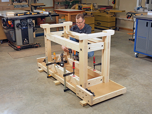
We’re nearly done building this heavy-duty shop fixture! Find a buddy to help you move the now much heavier (thanks to those vises!) inverted benchtop carefully to the shop floor, with scraps of wood underneath it to protect the top surface. Turn the bench’s base framework upside down, and move it into position on the benchtop. Adjust the frame so the top will overhang it evenly on the ends and so the tail vise assembly is carefully centered between the legs. Check to make sure the outermost dog holes are also clear of the long top stretchers and legs. When everything registers, drill pilot holes for 6″ lag screws into the benchtop at the eight screw holes you drilled through the long top stretchers. Drive a lag screw into each hole to attach the framework to the benchtop.
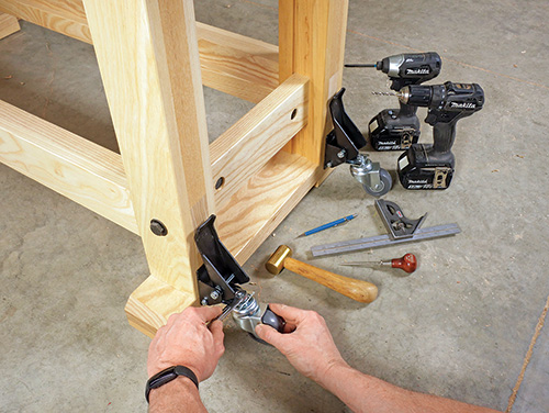
Now, with assistance, flip the bench upright onto its feet. I installed a set of Rockler’s workbench casters to the outside faces of the legs with 1-1/2″ lag screws and washers, following the instructions that come with the caster set. These flip up and down, making the bench easy to move around the shop.
I drilled two bench dog holes all the way down through the thickness of both faces of my tail vise; they align with the outermost rows of bench dog holes on the bench.
With that done, I used the four remaining MDF offcuts from the benchtop as doubled-up sections for the bench’s lower shelf, trimming their corners to wrap around the legs. It was a good way to add more weight to the bench’s undercarriage and put those leftover scraps to good use. However, you could also use a couple layers of 3/4″ plywood if you prefer, or even pieces of 2x dimension lumber. The choice is up to you for completing this utility shelf.
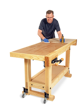
Complete this ambitious build by giving your new workbench several coats of a wipe-on finish. I used satin poly, but an oil/varnish blend such as Watco Danish oil would work great, too. Apply at least three coats to the bench’s top surface. A wipe-on finish will offer some protection against moisture absorption and spills without building to a slippery surface — that’s a no-no for workbench tops. It’s also easy to renew when needed by simply wiping more finish on.
Click Here to Download the Drawings and Materials List.
Hard-to-Find Hardware:
Heavy-Duty Cross Dowel and Bolt (1) #36073
Rockler Workbench Casters, 4 Pack (1) #43501
Rockler Heavy Duty Front Vise (1) #27838
Rockler 12″ Quick Release End Vise (1) #37180
Rockler Portable Drill Guide (1) #52885
Rockler Round Bench Dogs (1) #21868
Rockler 4-1/4″ Hold-Down Clamp (2)#90407
