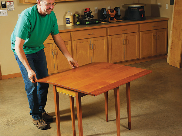
What first comes to mind when you think of a dining table? Likely something large enough to seat four or more people. But folks who are downsizing to smaller spaces, newlyweds and those settling into first apartments need a place to sit down for a meal, too, without it taking up too much space. Here’s one solution: a dining table made for two. When its drop leaves are up, this compact table offers a 36″ x 36″ tabletop: just enough for two chairs and place settings. Swing the tapered gate legs closed and drop the leaves, and this table’s top reduces to about half its raised width.
Building the project will give you a chance to put your tapering jig to work on the table’s two-piece legs. You’ll also gain some experience with rule joints and installing drop-leaf hinges.
I built my table from maple and cherry, but which two woods you choose is entirely up to you.
Making the Legs
We’ll start by building the legs, so rip and crosscut six leg blanks from 1-1/2″-thick stock, plus one extra that can serve as a scrap for adjusting your machine setups. (Note: I left my leg blanks overly long to reinforce the short-grain areas when chiseling the apron mortises square. It also allowed for “do-over” opportunity when tenoning for the feet.) Carefully mark the bottom ends of the table’s four primary legs for those 1/2″ x 1/2″ x 1″ tenons that will connect the feet. They are offset and should be located 1/4″ in from one corner of the leg blanks, because the four primary legs will receive two long taper cuts that reduce the legs to 7/8″ x 7/8″ at the bottom ends of the feet. The tenons for these feet must remain clear of the tapered areas that will be sawn away.
Mark one end of the two gate legs for 1/2″ x 1/2″ tenons as well. However, the gate legs will receive taper cuts on both of their side faces and the back face, with only the front face remaining flat. So, center these tenons along what will eventually be the untapered “show” face, and inset the tenons 1/4″ from it.
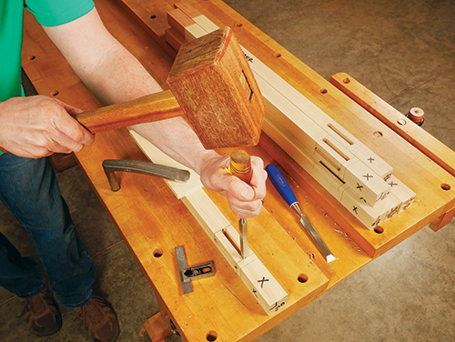
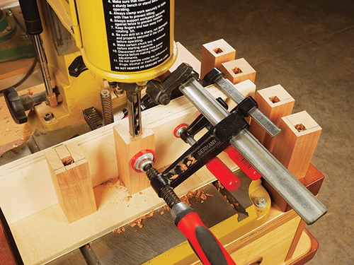
Next, prepare six blanks for the feet, and reference the location of a 1/2″ x 1/2″ mortise on the end of each one using the tenon layouts on the leg blanks as your guides. Bore these mortises a little more than 1″ deep at your drill press with a 1/2″-dia. Forstner bit or using a 1/2″ square chisel in a mortising machine as I did. Square up the mortises if you drill them.
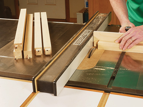
Head to the table saw and install a wide dado blade for cutting the bottom tenons on the legs. Carefully cut away the waste material around the tenons, backing up the workpieces with a miter gauge and sacrificial fence. Use the scrap leg as a guide for dialing in the correct blade heights for these cuts. Leave the tenons slightly thicker than will fit into the feet mortises. Then shave the faces of the tenons as needed with a sharp shoulder plane until they fit the feet mortises snugly.
Now, be sure to do this: mark each leg so you’ll know where the tenons are located once the feet are glued on. Without these references, and the tenons hidden inside the feet, you risk accidentally cutting through them when tapering the legs.
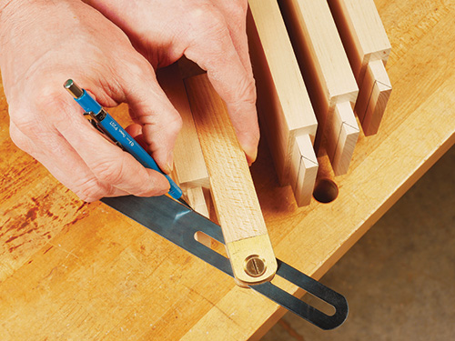
Glue and clamp the feet onto the leg blanks. When the glue dries, joint the leg faces flush, as needed, to flatten the interface between the feet and legs. If your legs are overly long, mark their final lengths now, to avoid mistakes. Then lay out a pair of 3/8″- wide, 3″-long centered mortises in the primary legs for housing the tenons of the long and short aprons. Locate these mortises 1/2″ down from the tops of the legs. Pencil a centered mortise of the same size on what will become the back face of the gate legs. Mill these mortises 1″ deep at the router table or on your hollow-chisel mortiser. If you rout them, chisel their ends square. At this point, I cut my legs to final length to remove the excess material above the mortises.
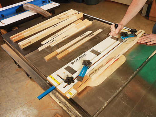
Now, carefully mark the six legs for their respective taper cuts. The tapers begin 4-1/4″ down from the top ends. Set up a tapering jig and rip the tapers at your table saw or band saw. (Note: Be sure to taper the back face of the gate legs first, then the two side faces; if you accidentally taper the side faces first, you’ll remove the bearing surface required to make the back taper cut correctly.)
Building the Base
Prepare blanks for the long and short aprons as well as the two gate leg supports. Mark both ends of the aprons and one end of each support for 3/8″-thick x 15/16″-long x 3″- wide tenons. Cut the tenons to shape with a wide dado blade, testing your setups first on a scrap. Plane them as needed to create a good friction fit in the leg mortises. Then miter-cut the ends of the primary leg tenons at 45° but without shortening their lengths — they will butt against one another at the bottoms of the leg mortises when installed.
When the gate legs are folded against the table, they nest into a 1/4″-deep recess in the outside face of the long aprons to create clearance for the drop leaves to pivot down fully. Refer to the Drawings to locate these 1-9/16″-wide recesses. Cut them with a dado blade, and plane or file their bottoms smooth.
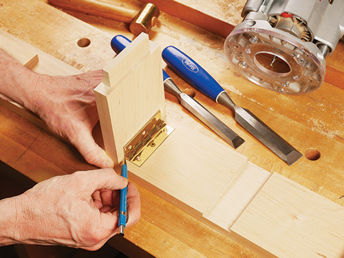
The long aprons also receive mortises for a 3″ butt hinge that pivots the gate legs open and closed. In this project’s application, both the hinge leaf and the knuckle must be mortised into the apron face. Draw a layout line across the width of the aprons, 5-1/16″ back from the gate leg recesses. Align the back edge of the hinge knuckle flush to this layout line, and scribe around the hinge leaf to lay out the mortise. Rout or chisel the mortise to a depth that matches the hinge leaf thickness. Now, set the hinge into its mortise and open the top leaf to 90°. Set the gate leg support against the apron and hinge leaf, and draw or knife a corresponding hinge leaf mortise onto the supports. Rout or chisel these mortises to shape. I also detailed the aprons and supports with a 5/16″ bead profile routed along their bottom edges. It adds a nice shadowline.
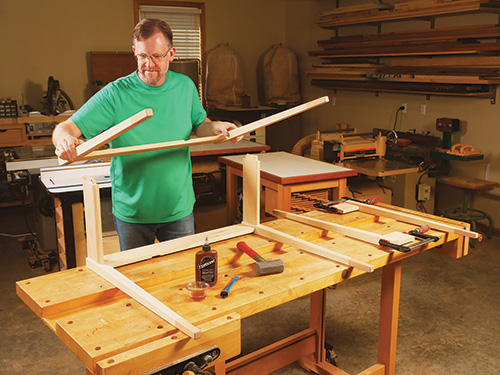
Finish-sand the legs, aprons and supports, then glue and clamp the four aprons and primary legs together. Do the same for the gate legs and their supports. When the clamps come off, install the gate legs and hinges with a couple of screws to verify that these legs fold correctly into their apron recesses.
Adding a Web Frame
We’ll connect the table’s base to the top with screws driven through a web frame that’s mounted inside the base. I made my web frame from 7/8″-thick stock in order to be able to use 1-1/2″ screws for attaching the top but without them accidentally poking through it.
Start building the web frame by cutting its rails to size, then plow a 5/16″-wide, 1/2″-deep centered groove along one long edge of the rails. On the long edge opposite this groove, trim 3/8″ off of each corner of the rail to form a notch, so it will wrap around the inside corners of the legs. Now clamp the rails into place on the aprons temporarily so you can verify the final length of the stiles — they will be 1″ longer than the distance between the rails.
Rip and crosscut the stiles to size, and raise a 5/16″-thick, 1/2″-long centered tongue on each end. Glue the rails and stiles together so the outer stiles are flush with the ends of the rails and the third stile is centered on the web frame’s length.
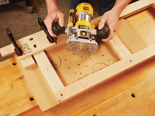
Once the frame joints dried, I drilled a centered screw hole through the middle of each stile and routed six slotted holes in the rails for the tabletop installation screws. The slotted holes, which should be oriented parallel with the web frame stiles, will enable the tabletop to expand and contract as it undergoes seasonal humidity changes.
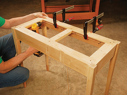
Install the web frame inside the table base with #8 x 2″ screws driven through the bottoms of the frame grooves and into the aprons. I located the frame about 1/16″ below the top edges of the aprons so the tabletop will be drawn down tightly to the aprons when it’s eventually attached to the web frame.
Rule Joints: A Two Bit Overview
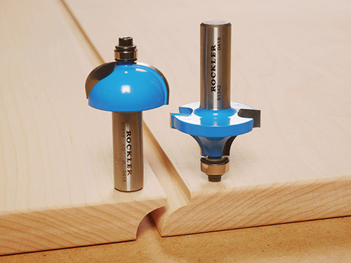
While rule joints were once cut by hand with profiling planes, these days they’re quite easy to machine with a matched set of router bits sold as a set. You’ll use the roundover bit to mill a roundover/fillet profile along the edges of the tabletop’s center panel. The fillets form “flats” closest to the panel’s top face. When done on a router table, the bit’s orientation requires that the panel be routed top-face-down. If you use a handheld router, machine the center panel so it’s top-face-up.
The mating drop-leaf profile is made with a cove bit so the drop leaves can nest against the center panel but also rotate down and away from it. Here, the drop leaves face up if you cut the profiles at the router table. Alternately, flip the panels facedown for cutting the coves with a handheld router. It’s a good idea to make a test joint, label the panels and, of course, stay focused on the task to avoid mistakes.
Forming the Rule Joints
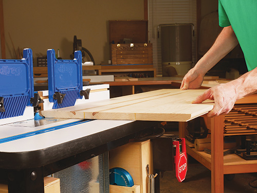
Glue up blanks for the center section of the tabletop and the two drop leaves with their contrasting trim boards. While I trimmed my three blanks to final width at this stage, to prepare for routing their mating rule joints, I decided to leave them a couple of inches overly long in order to wait until the drop leaves were installed on the tabletop’s center panel; this way I could trim the tabletop to final length with all three components and the hinges in place.
Your next order of business is to rout the rule joints that enable the drop leaves to rotate past the wide center panel. Rockler provides a downloadable PDF article about drop-leaf joints and hinge installation that proved extremely helpful for milling these aspects of the table top.
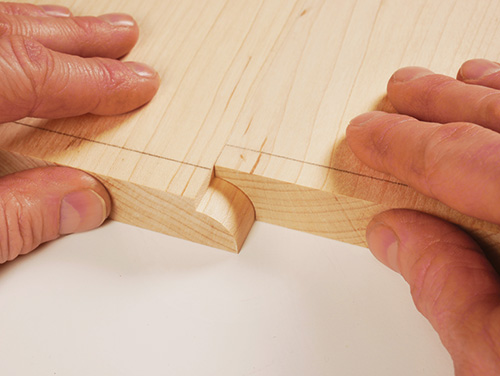
Thoroughly familiarize yourself with that PDF and the bits, then cut a test rule joint on a couple of scrap pieces so you’ll be able to use them as guides for setting the bit heights again when you rout the actual tabletop parts. A practice run is always a good idea anyway when you’re routing joinery.
The roundover/fillet profile (on the tabletop center panel) is the first profile to machine. After some trial and error, I learned that a 3/16″-deep “flat” fillet portion at the top of this profile creates a well-functioning rule joint with Rockler’s router bit set. Also, be aware that if you rout the roundover/fillet profile on a router table as I did instead of with a handheld router, the top face of the panel should be oriented down against the router table. Alternately, rout the panel with the top face up if you use a handheld router.
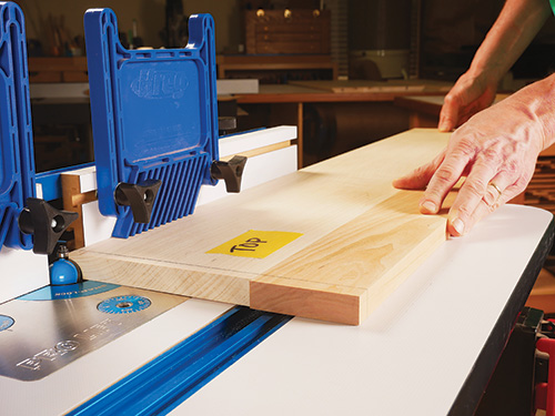
The drop leaves receive a complementary cove profile to complete the rule joint, so switch to that bit and complete this step of the milling process. On a router table, rout the drop leaves with their top faces up. Rout into the bottom face instead, if you do this step with a handheld router. You’ll know you’re on the right track if the roundover and cove profiles fit together and the faces of the test parts are flush when resting on a flat surface. As soon as the test joint is dialed in, go ahead and rout the actual table parts.
Mortising Drop-leaf Hinges
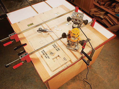
There’s just no simple way to explain the milling and installation process of drop-leaf hinges that will do as much justice to the subject as a well-rendered illustration can. So, here again, study the drawings provided on Rockler’s PDF carefully to get the lay of the land.
With that measurement determined, I clamped the three sections of the table top together, penciled the six mortise locations (see the Drawings for those positions) and milled them 1/16″ deep using a shop-made plywood template and a piloted hinge-mortising bit in my router. Strips of double-sided tape held the template securely in place as I routed each mortise and squared up its corners. But, using a template for this process isn’t make-or-break — you could knife the hinge locations and hog out this waste with a handheld router or even chisel them entirely, if you prefer.
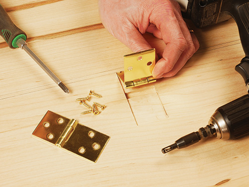
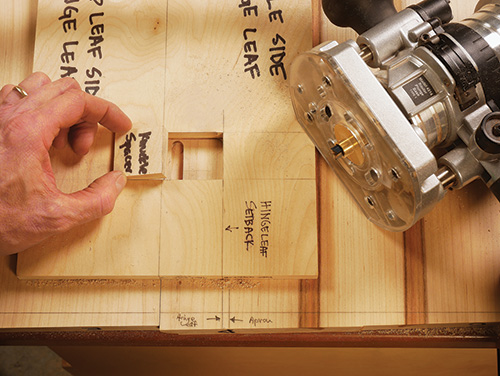
One benefit to using a hinge template, however, is that drop-leaf hinges must be installed with their knuckles facing inward toward the panel — unlike typical butt hinge configurations. So, a deeper channel must be routed or chiseled into the hinge mortises to fit the knuckle. I was able to simply insert a spacer inside the template to locate my router, a guide collar and 3/8″ straight bit for milling those knuckle recesses.
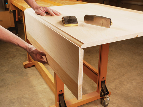
Once all six drop-leaf hinge mortises were machined, I installed the hinges temporarily to test the action of the rule joints. Be prepared for a bit of rubbing at this stage. You may need to rout a slightly deeper cove profile or sand and file the bottom edge of the roundover profile a bit to improve the action. Once the joints function smoothly, trim the tabletop to final length. Then remove the hardware, ease the sharp outside corners of the drop leaves and soften all of the long edges with a roundover bit, block plane or sanding block. Final-sand the three tabletop components.
Fast Forward to an Aged Finish
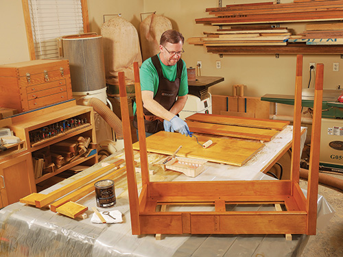
While I like the look of “fresh” blonde maple, I also appreciate the amber patina it takes on with an oil-based or shellac finish after decades of oxidation, sunlight exposure and use. So, I decided to speed up the aging process with a coat of blended dye stain to simulate the amber tone. I started with General Finishes yellow dye stain and added medium brown dye to it, drop by drop, until I achieved the color I wanted. Three coats of General Finishes waterbased Enduro-Var topcoat sealed in the dye and also helps to warm up the wood tone. It dries super fast and stands up well to normal wear-and-tear.
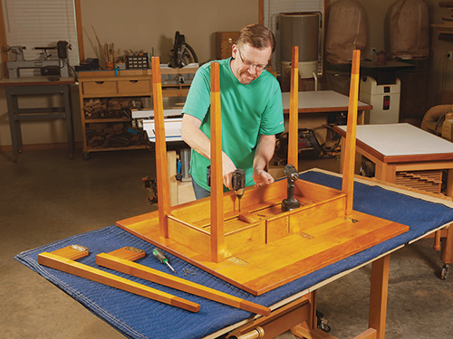
When the finish cures, reassemble the tabletop’s hinges and drop leaves. Center the base on it and drive nine 1-1/2″ washerhead screws through the holes in the web frame to secure the parts. (I used coarse-thread pocket screws for this job.) Center the screws in the slotted holes. Then mount the gate legs and hinges to the long aprons to wrap this compact table project up.
Download the Article on Drop Leaf Hinge Installation.
Click Here to Download the Drawings and Materials List.
Hard-to-Find Hardware:
Two-piece Drop Leaf Rule Joint Bit Set (1) #26318
Drop Leaf Hinges for Shaped Edges (3 pr.) #29256
Rockler Taper/Straight Line Jig (1) #29256
Freud Beading Bit (1) #31613
