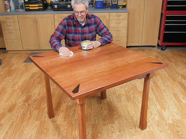
When you stop and think about it, we spend a good bit of our lives sitting at our dining tables. It is a place where family spends time together eating, doing homework, playing games, paying the bills and more.
It is a valued place in most of our homes and for that reason, it makes some sense to have a quality table as the nexus of all this togetherness. This table project here is only 40″ square, so it would not work for seating a big family.
But it is perfect for an apartment — a mom, dad and a young one or two. When it’s time to progress to a larger dining table, move this one to a family room and voilà … you have a game table! One thing is certain: with its substantial white oak construction, this table will take the wear and tear of family life, perhaps for generations.
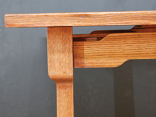
I mentioned that it is made from white oak lumber; the quartersawn stock is 1-1/4″ thick for the tabletop, the legs are 2-1/2″ in section and the aprons are 3/4″ thick. There are four corner braces hidden under the top that add significant strength to the piece. It is indeed built to last.
We borrowed the cloud lift motifs on the aprons and the gentle curves on the legs from the Greene brothers. It is not a Greene and Greene reproduction by any means, but their inspiration adds stylish details to this table’s relaxed design.
Templates are the Key to Success
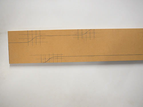
Making multiple matching curved pieces like these legs and aprons is best done by employing templates to guide your cuts, be they on the band saw or with a guided router bit. Use the gridded drawings to make your own.
Soon Rockler will have templates for this table for sale as well. However you start, making these templates accurately from MDF will get you a long way down the road to success.
Selecting Stock, Harvesting Parts
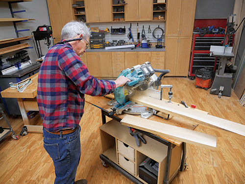
I ordered my supply of quartersawn lumber surfaced on two sides at 1-1/4″ thick and in random widths and lengths. I was disappointed with the amount of sapwood I found in the boards, so part of my stock preparation was avoiding the sapwood as I harvested pieces for the legs and the tabletop. Unfortunately, I was not 100 percent successful in my goal. The leg’s final dimensions are 2-1/2″ square in section and 29-3/4″ in length. I ripped enough stock to make five legs, because if a flaw or a significant machining problem were to come up, I would not have to go back and glue up another one. I was glad I did this for a couple of reasons I’ll share later.
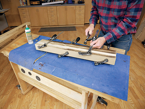
I ripped the stock to 2-9/16″ wide and a hair longer than their final length. I glued them up two at a time using Titebond III for the job. I like its longer open time and the fact that it is a bit darker in color, perfect for white oak. Of course there was the fifth leg to glue and clamp by itself.
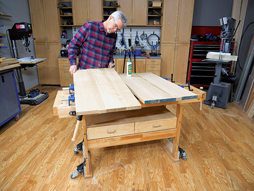
Selecting the pieces for the tabletop had its challenges. First, there was the sapwood to avoid. Next, the figure of the boards varied significantly in terms of how dramatic the medullary ray flakes presented. A couple of boards had very pronounced flake figure, one had less and another had almost none. So I decided to put the highly figured lumber in the center of the top, use the less figured stock on either side of those pieces and arrange those with little flake at the edges.
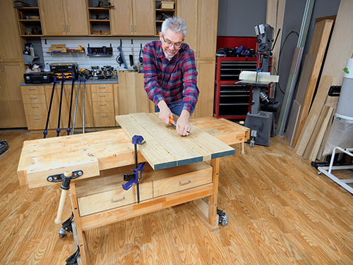
I would have preferred a uniform flake pattern across the entire top, but that was not to be, so this was my best option. After I had cut the pieces to rough length, squared up the edges on the jointer and removed the sapwood, the top was about 3/4″ too narrow. (Sometimes a guy just can’t buy a break!) So I processed another piece of stock, ripped it in two and located those pieces just inside of the outermost boards in the glue-up. The pattern of symmetrical figure looked good to me.
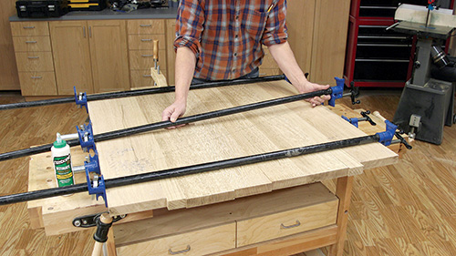
Even at just 40″ square, this thick tabletop weighs a good bit, so I chose to start the assembly process by gluing up two halves of the top. After the joints cured, I flattened and sanded them smooth. Then I glued the two together to complete the blank. That allowed me to only have to align one glue joint for the final clamping step — much easier. Working smart is something I have learned to appreciate over the years.
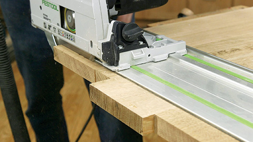
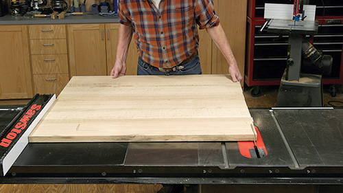
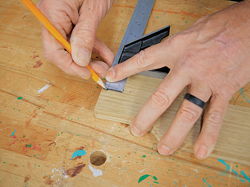
Trimming the tabletop down to its final size was a two-step process. First I marked a line at 90 degrees to one edge of the table. Then I used a track saw to cut the marked edge. If you don’t have a track saw you could use a handheld circular saw with a fence clamped to the tabletop, or even a handheld router guided along a fence. With that done, I hefted the tabletop over to the table saw and cut the opposite edge parallel.
I took a few moments to use a 4″ x 24″ belt sander to clean up the center glue line and ensure the top was flat by sanding across the grain. I then sanded the top up through the grits to 150 and set it aside to move on to the legs and aprons.
Shaping the Gently Curved Legs
The shape of these table legs suggests Greene brothers design. The Greenes were strongly influenced by the Asian exhibits they found at the World’s Columbian Exposition of 1893 in Chicago. The sweeping curves in their work has a distinctly Asian feel, and these table legs evoke the same.
I began the machining process by squaring my glued-up leg blanks. I ran one edge-glued face of each leg over the jointer to create two clean 90-degree faces per leg. Then I stepped to the planer so I could clean up the other joined face and square the legs perfectly. Using my leg template to set up a stop on the miter saw, I cleaned up each end of the legs by cutting them to length. Then it was time to start shaping them.
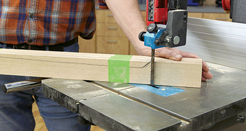
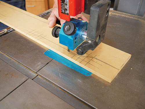
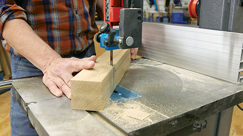
Start forming the two long curves on each leg by scribing the template shape on two adjacent leg faces and toting them over to the band saw. Then, as you would when making a cabriole leg, carefully cut just outside the lines on one of the leg faces. I installed a 1/4″ blade in order to make these cuts accurately, especially the tight curve at the top of the legs. With the first cut done, grab the waste piece you just removed, and tape it back in place. Then cut the second marked face in the same manner. Repeat this process for all four legs to ready them for some template-routing.
Flush-cut Routing in Two Stages
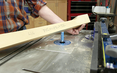
One challenge with shaping the legs on the router table is that my longest bit for the task had a 2″ cutting limit. However, including the 3/8″ thickness of my template, the overall thickness I would need to accommodate for routing was 2-7/8″. My 2″ bit literally would not cut it. That’s why shaping each face required two operations. Start by chucking a 3/4″-diameter, 2″ pattern router bit (with the bearing near the shank) into the router table.
Attach the template to the leg blank with double-sided tape and carefully remove the material with a slow, controlled pass. Take extra care at the tight radius near the top of the leg. One of my legs fractured during that cut, breaking off about a 1/2″ chunk of oak. The extra leg blank then came to the rescue! (I could have repaired the tearout, but it would have been time-consuming.) Template-rout both contours of each leg this way, then switch to a flush-trim bit with the bearing at the tip. Use it to trim off the small bit of remaining waste with the bit’s bearing rolling along the routed portion of the first passes.
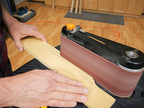
Next, I used a benchtop belt sander to smooth the legs and remove the machining marks. Be careful to keep a clear break where the leg’s curve transitions to the square “foot” of the leg. After they are sanded smooth, set the legs aside.
Making the Cloud Lift Aprons
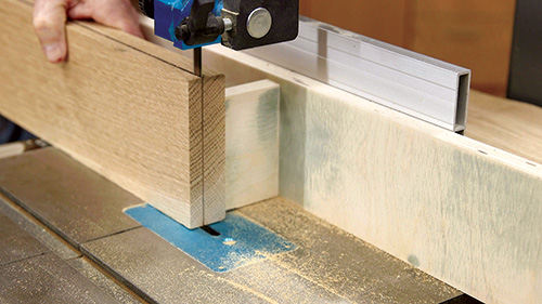
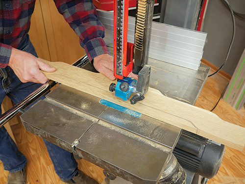
The first order of business when making the aprons is to cut the stock to length and width. Since I had purchased all of my lumber at 1-1/4″ thick, I needed to resaw them to their 3/4″ thickness. You can see that with the aid of a “point” style fence on the band saw, removing the extra wood was an easy task. I completed this thicknessing and cleaned up the sawn face of the pieces at the planer.
The tabletop will attach to the aprons with metal tabletop fasteners. To make that possible, I plowed a 1/8″-wide, 5/16″-deep saw kerf the length of the aprons while they still had flat edges. You can find the location for this kerf in the Drawings.
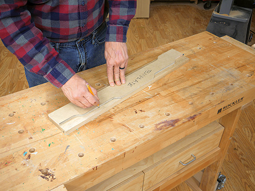
Shaping the aprons will repeat most of the same steps you took to form the legs. Prepare for template routing by tracing the apron shape onto the boards. Make sure the saw kerf is properly located when you draw the template. It needs to bisect the top cloud lift.
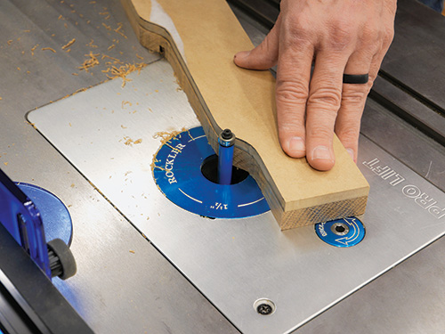
Move back to the band saw and rough out the shape of the aprons. Cut about 1/16″ outside of the pencil lines. Then head back to the router table one more time so you can trim off the waste using the same flush-trim bit you used to machine the legs. Attach the template to each leg with double-sided tape for this process. You’ll find this operation is less of a heavy lift when compared to the legs — thinner stock makes the template-routing process more manageable.
Joining the Legs and Aprons
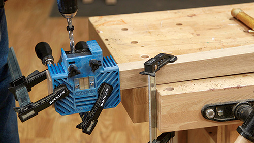
To attach the legs and aprons, I tried out the latest version of Rockler’s Beadlock jig and used the premade tenon stock. I was able to form the mortises with the new jig pretty effortlessly. I chose to use the 3/8″ thick tenons for these joints, and they were really solid when I was done. Here’s how to use the jig.
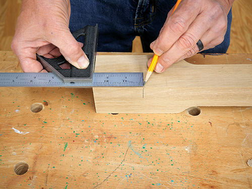
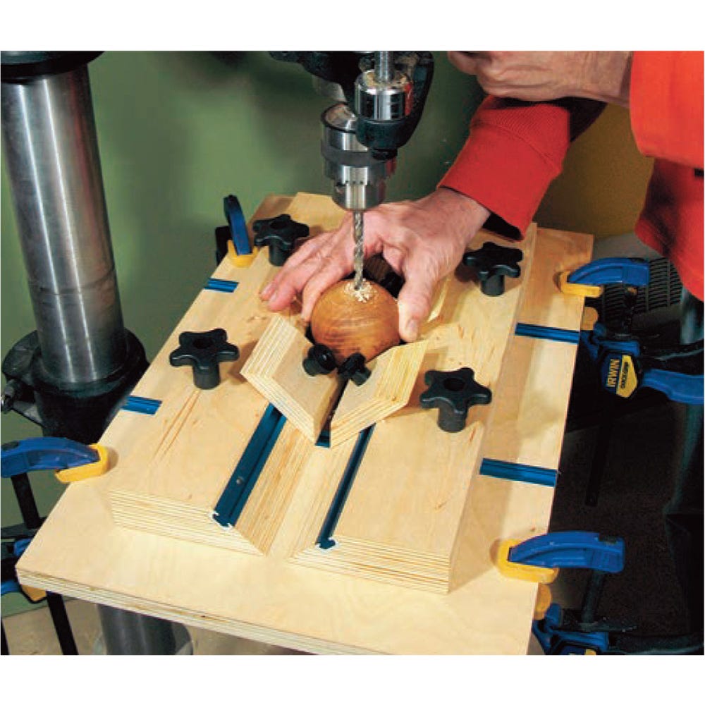
With Beadlock you use a standard twist drill bit to drill out the mortise waste in a series of side-by-side holes, guided by a metal bushing in the jig. In this regard, it’s very much like the Kreg pocket-hole system. Here, the bushing is held in the jig by two bolts. There are two positions — A and B — and you start out (in the case of the 3/8″ tenon stock) by drilling three 3/8″-diameter holes. There is a depth stop that you locate on the drill bit to control the depth of the mortise. After you drill the three holes at position A, you shift the guide to position B to drill out two more holes. This second step clears out the remaining material left between the three original holes to create a multi-ridged mortise that perfectly fits the shaped tenon stock.
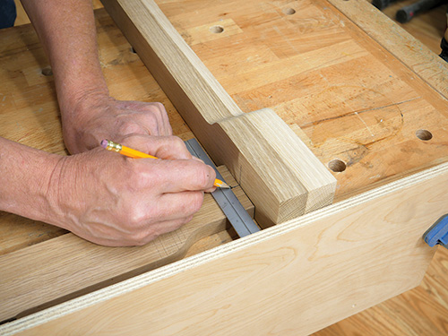
The Beadlock kit includes shims of differing thicknesses that allow you to place the mortise where you need it in stock of different thicknesses. Here I centered the mortises in the 2-1/2″-square leg tops and 3/4″-thick aprons simply by switching out the shims. For this table, it is important to align the top of the apron’s center cloud lift with the top of the legs. This will allow you to tightly secure the tabletop to the base using the tabletop fasteners. To do that, I bumped the top of the legs up to a long straightedge that I had clamped to my workbench. Then I put the apron against the straightedge, mimicking how The it should align when assembled. With that done it was easy to properly locate the center points of my mortises for registering the Beadlock jig. And here’s another important note: Be certain to place the mortises on the proper faces of the legs. There are two outside faces of the legs — the shaped ones — and two inside faces — the flat ones. Please don’t ask why I am making such a big deal about this…
Other loose-tenon systems such as Festool Dominos would work on this table, as well as dowel joints or any other joinery methods you are comfortable with. But I did find the Beadlock system to be accurate, easy to use and affordable.
Final Steps to the Finish
With the mortises drilled, you are nearly done with the machining process. I thought it prudent to dry assemble the leg set at this point in order to make certain the joinery was sound. With the legs and aprons clamped together, I went ahead and made the corner braces and temporarily mounted them on the aprons. I marked the inside of each apron and cross brace so that I was confident they would go together smoothly when it came time for final assembly.
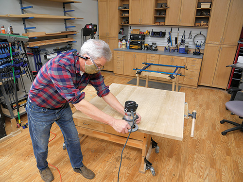
Looking at the tabletop, I decided that I wanted the edges rounded over slightly, so I used a 1/8″ roundover bit chucked into a handheld router to complete that task.
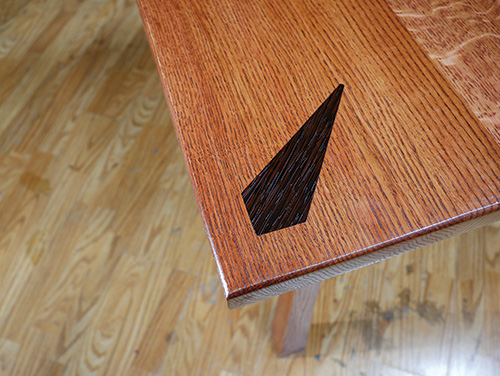
table would look great without them.
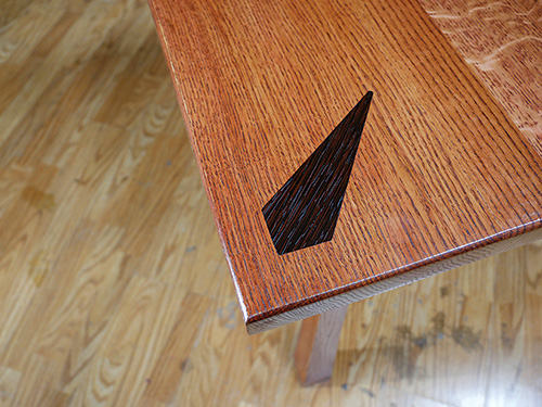
My next design step is entirely optional. I decided to put some accent inlays in the corners of the tabletop. They are a very basic shape — I’ll call them a stretched diamond, but some cheekier members of the staff call them the carrots. They are fairly easy to inlay the old-fashioned way. But once again I decided to give the Shaper Origin a spin on this table project.
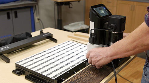
I chose 1/8″ wenge I found at Rockler for its dark contrasting color along with the red highlight it displays. Truthfully, I think the table would look just lovely without the inlays. So don’t let them throw you off if you don’t like how they look.
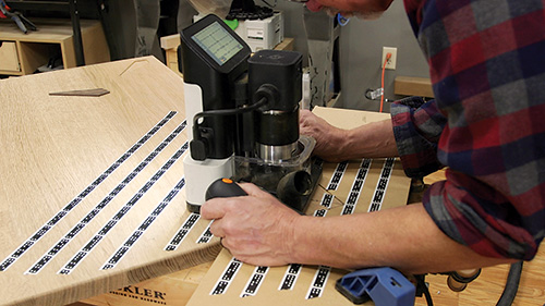
Once the stretched diamonds were glued in place, it was time for more sanding. I sanded the table all the way up to 400-grit. While others may think that’s excessive, I prefer to have a super smooth surface to finish. I broke the edges of the legs with 320-grit by hand to remove the sharp edges.
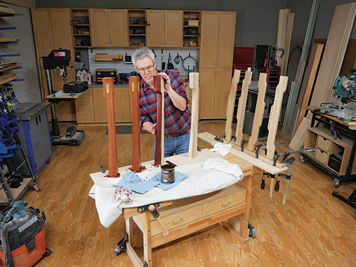
I chose to apply the stain and finish to the table components before assembling them. Working on individual pieces is so much more controllable and you can inspect them very closely as you work. I find it avoids drips and errors. To make that happen, I masked off the mortise areas on the legs with painter’s tape. I mounted the legs on a scrap piece of plywood by driving a single screw up through the plywood into the center of the bottom of the legs. For the aprons, I temporarily put short Beadlock tenons in one end and then clamped the tenon stock between two boards. Then those boards were clamped to another piece of plywood. It may sound like a lot of prep work, but it wasn’t hard, and I think I got great results because of the extra effort at this stage.
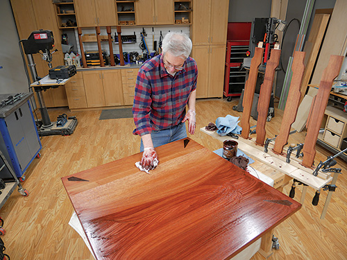
I applied Old Master’s Red Mahogany wiping stain to all the pieces and let it dry. Following that I brushed on two coats of Zinsser® SealCoat™ shellac. Having taken the time to sand the surface so finely, the shellac laid down really well.
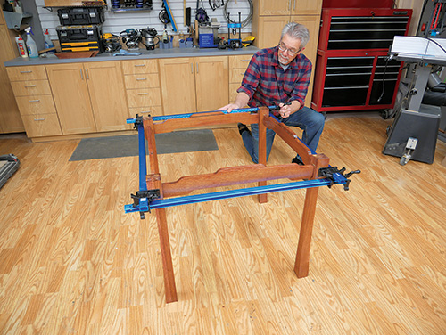
When that cured — and shellac dries fast — I wiped on three coats of polyurethane. I think the stain, shellac and poly combination finish makes this table look like a million dollars.
So that’s it. Considering that it’s a fairly basic table, it was still a pretty intricate build and a truly enjoyable experience. As I mentioned at the beginning of this article, while the table is compact, it is substantial and built to last. If you work carefully and patiently on it, generations of your family will be able to sit at this beauty and enjoy all the ways we fellowship around a table, whatever those may be.
