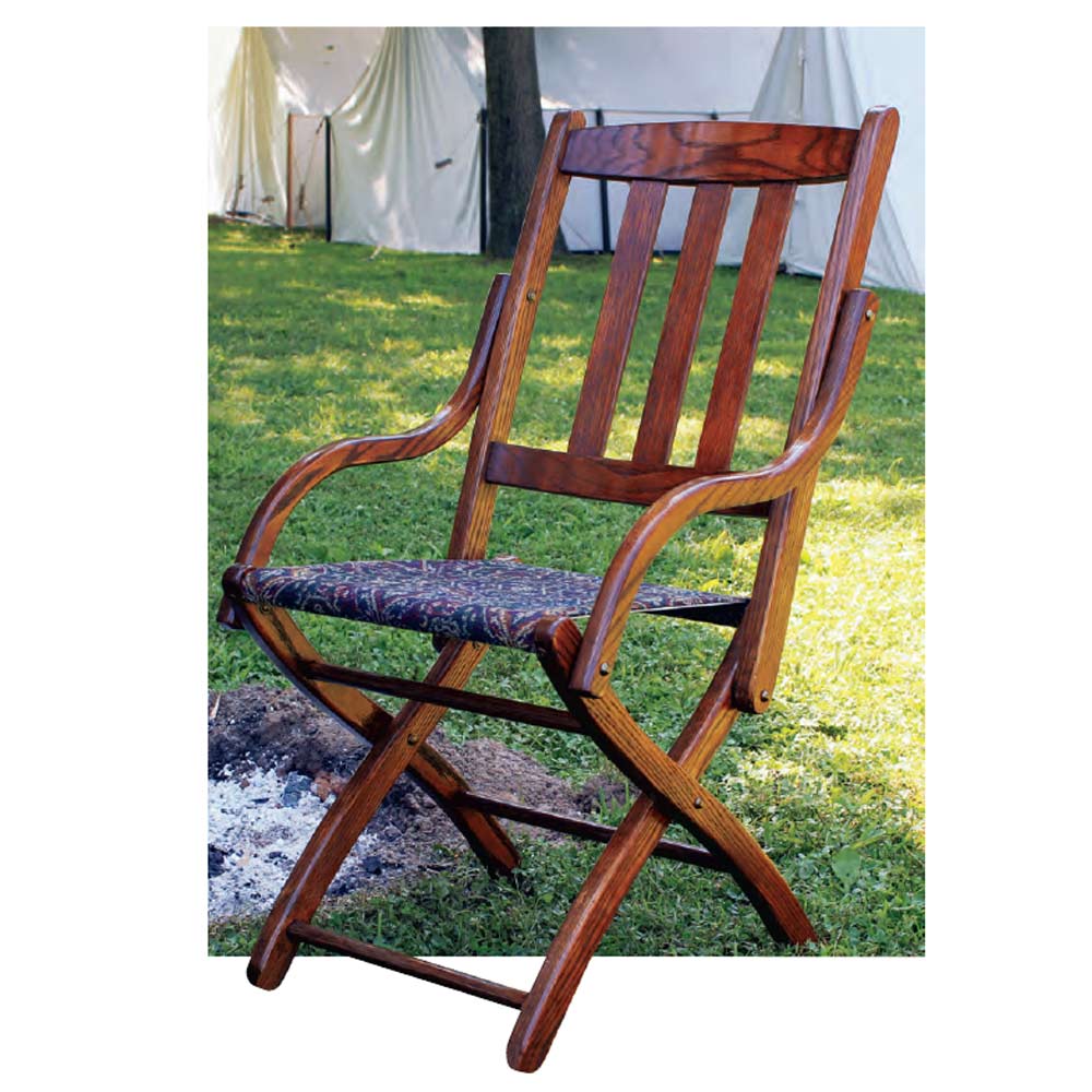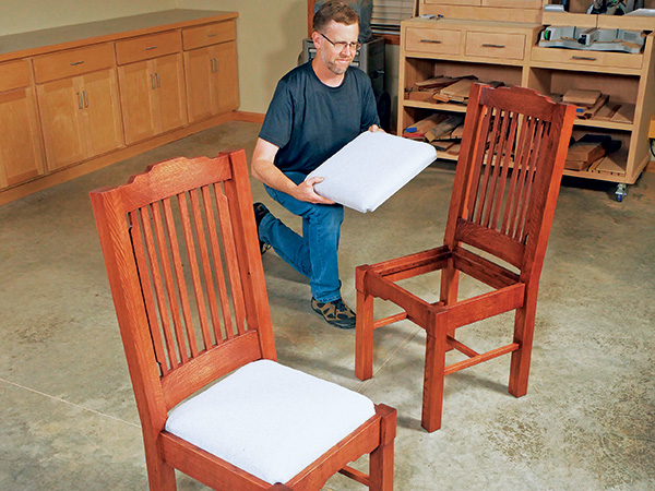
Woodworkers often hesitate to build chairs, either because the construction is complicated or they’re concerned the final product won’t be comfortable to sit on. But let me assure you, this chair’s straightforward design isn’t hard to build if you have moderate woodworking experience, and its Beadlock floating tenon joinery couldn’t be simpler to master. The tilted backrest, curved back rails and amply padded seat make this chair easy on your backside, too.
Starting with the Legs
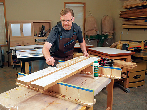
Glue up 2″-thick blanks for the front and back legs from 5/4 stock planed to 1″. A blank measuring 6″ x 46″ will yield both a front leg and a back leg. Once the blanks come out of the clamps, flatten their edges on a jointer or with a plane.
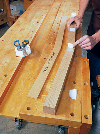
Use Rockler’s cardboard templates to trace the front and back leg profiles on the blanks. Or create your own template by enlarging the gridded drawing. When drawing the back leg shapes, position the template so the front edge of the lower portion of the leg is flush with the blank’s edge. This way, the upper angled portion of the legs runs diagonally across the blank.
At the band saw, cut the four legs to rough shape, sawing about 1/16″ outside your layout lines.
Use your back leg template again to form a rigid template from a piece of scrap plywood or MDF that’s at least 1/4″ thick. We’ll use this rigid template for routing. Carefully cut the template out, following the layout lines. Sand the template’s edges smooth and flat.
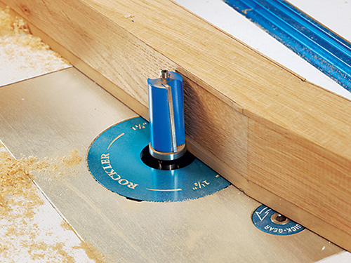
Adhere the back leg template to one of the leg blanks with double-sided tape so the rough-cut edges of the blank extend beyond the edges of the template. Install a long pattern bit (bearing on the shank) in your router table — I used Rockler’s Double Bearing Flush Trim Bit with the end bearing removed. Adjust the bit’s height so the pilot bearing will roll along the edge of the template. Start the router and feed the workpiece and template along the bit, trimming off as much of the overhanging waste as the bit can reach — most pattern bits won’t extend all the way across a 2″-thick workpiece.
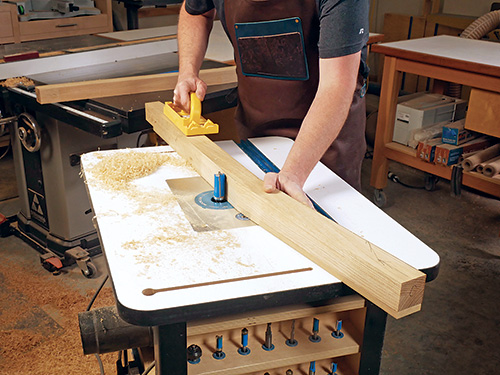
While your feed direction should be from right to left as usual, try at all costs to avoid routing against the grain direction (where the upper portion of the back leg crosses the wood grain at an angle). Run the router at its highest speed and feed very slowly to prevent the bit from tearing out the wood grain in these areas. Then raise the bit and make a second pass to remove the rest of the waste. Repeat the template-routing process on the second back leg.
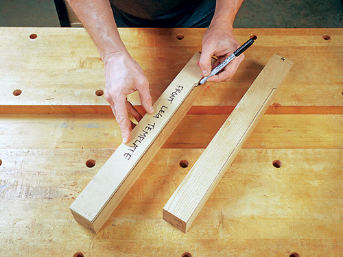
With that done, create a plywood or MDF template for the front legs using Rockler’s cardboard front leg template as a pattern or by enlarging the gridded drawing.
Rip a pair of front leg blanks to 2″ wide from the stock remaining from the back leg blanks. Cut these blanks 1/2″ to 1″ overly long, and trace the cloud lift profile onto the front face of each leg blank. We won’t cut and template-rout this front edge to shape until much later in the building process, but marking it will help keep the legs’ orientation clear and avoid mistakes when marking and cutting the chair frame joinery.
Decide which legs will be left and right for your chair or chairs, and mark the four legs on their ends so you can avoid confusion as you work.
Drilling Mortises
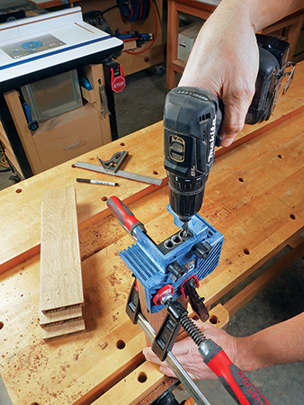
Make blanks for the front, back and side seat rails from 3/4″-thick stock. Use Rockler’s cardboard template or the gridded drawing to draw the cloud lift profile onto the bottom edge of the front seat rail.
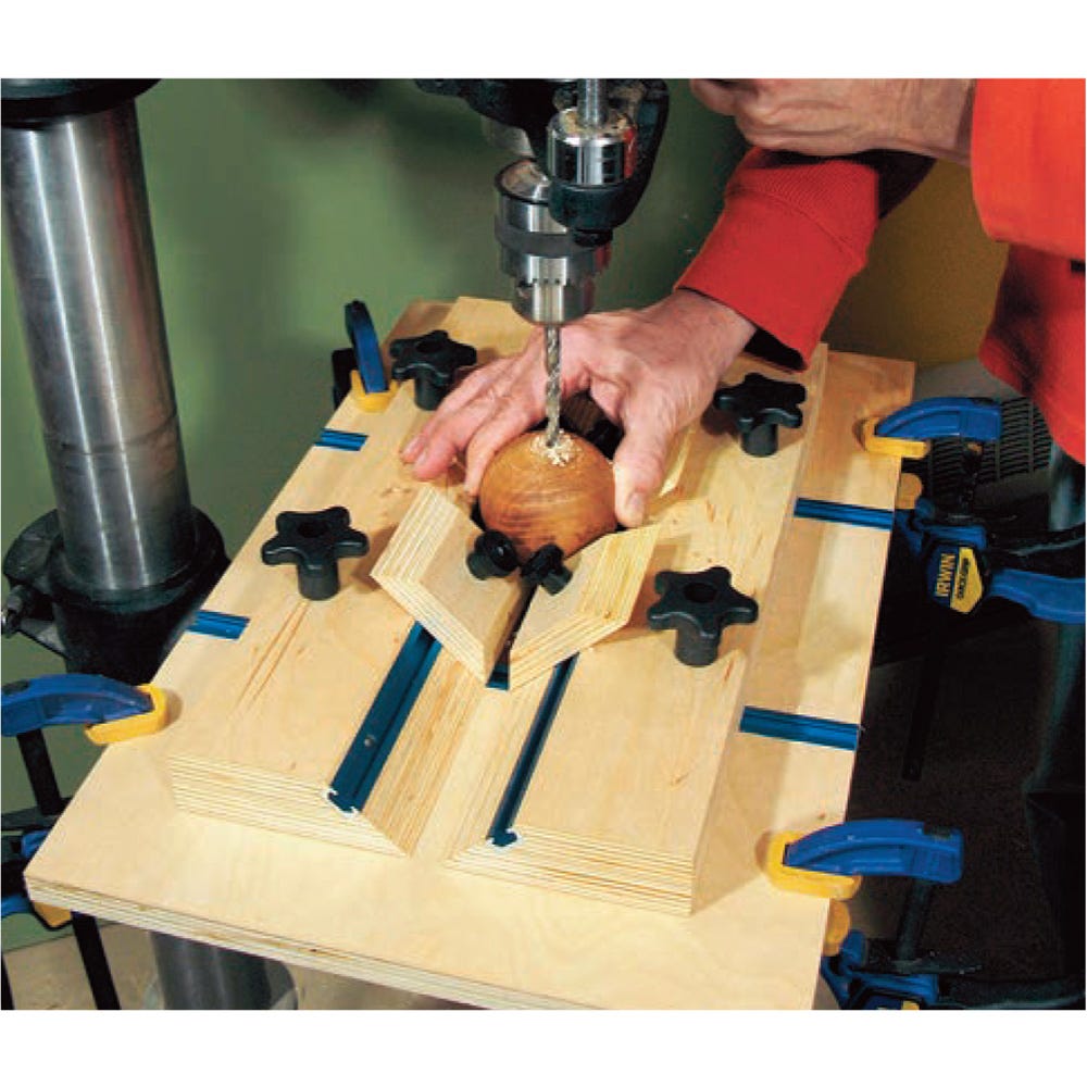
We’ll be using Rockler’s 3/8″-thick hardwood Beadlock loose tenons to assemble most of the major joinery of this chair. Rockler’s Beadlock system is very easy to use. If you can drill holes with a drill/driver, you can produce sturdy leg/rail connections without other tools. The Beadlock drilling jig simply clamps onto a workpiece, and shifting a hardened drilling guide within the jig to two positions — A and B — enables you to drill a series of side-by-side holes to create precise mortises for the premade Beadlock tenon stock. Once a pair of mortises are drilled for a joint, assembling legs and rails is as easy as cutting the tenon stock to the correct length and gluing them into place.
We’ll use a pair of Beadlock tenons to connect the seat rails to the legs at every joint. Mark a pair of mortise centerlines 15/16″ in from the top and bottom edges of each of the four seat rails on their ends. Now carefully transfer these layout marks directly from the seat rails onto the appropriate leg faces. On the front legs, plan for the extra part length to be at the top, and mark the mortises below it.
With the 3/8″-hole guide block installed in the Beadlock jig, bore both mortises into the ends of the seat rails. For each mortise, drill the three “A” series holes first, then the two “B” series holes to complete the five-hole mortise shape. Drill these 16 mortises 1-1/4″ deep, using the stop collar provided with the Beadlock drill bit to control the drilling depth. Clean out all the waste inside.
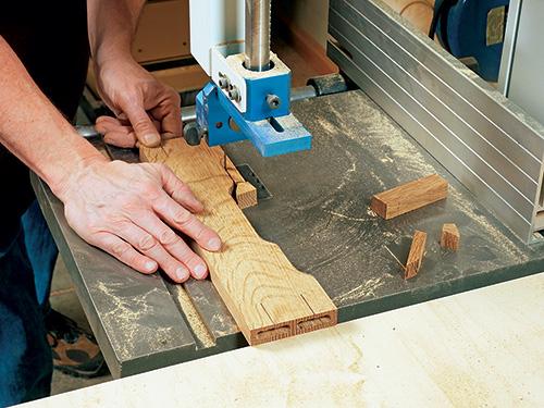
Now carefully cut out the cloud lift profile on the front seat rail at the band saw or using a scroll saw or jigsaw. Sand the profile smooth, up to the layout line.
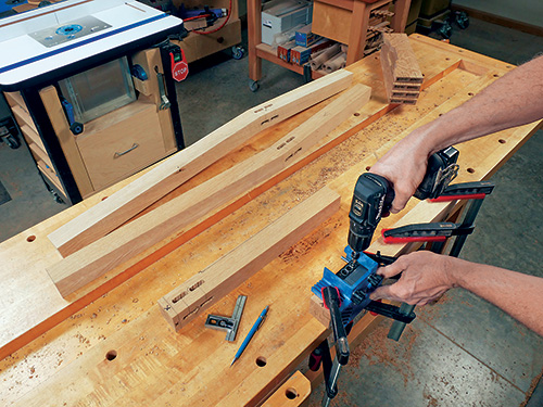
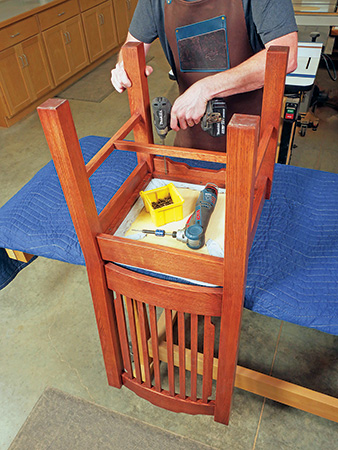
When the seat rail mortises are done, you can drill corresponding pairs of mortises in the front and back legs. To space these correctly, install 1/4″ and 1/2″ plastic Beadlock spacers inside the Beadlock jig behind the steel drilling guide. Clamp the jig against the inside faces of the legs for this operation. Bore the leg mortises 1-1/4″ deep for the front and back seat rails. Change the drilling depth to 7/8″ when you bore the side seat rail mortises into the legs.
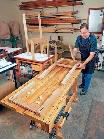
Next, crosscut eight Beadlock tenons for each chair to 2-1/2″ long for the front and back seat rail joints, and make eight 2-1/8″-long tenons for the side seat rail joints. Dry fit the legs and seat rails with tenons inserted in the joints, to make sure these joints come together easily and close fully when you clamp them. If all looks good, disassemble the parts so you can trim off the extra material from the tops of the front legs.
Making Crest and Back Rails
The 7/8″-thick crest and back rails are curved on their front and back faces to make the chair back more comfortable to rest against. There are numerous ways to create blanks for these rails, including steam bending or gluing many thin laminations together over a curved form. But for ease of construction, I chose to cut them out of 8/4″ solid stock instead. If you decide do the same thing, prepare a 2″-thick blank for each of these rails, using the Material List dimensions.
The curved profile of these rails will require nearly the full thickness of these blanks, but we’ll need to reuse the front and back offcuts several times in the overall machining process. So to thicken and strengthen what will be the back offcut, face-glue a piece of scrap hardboard or thin plywood to the back face of each blank (you can see it clearly in the photos).
Trace Rockler’s curved, C-shaped cardboard template for the crest and back rails onto the top edge of each blank, or draw the shape from the gridded pattern. Align the front edges of the template with the front corners of the workpieces when laying out the part shapes. Then draw the cloud lift profile on the front face of the crest rail workpiece.
Mark the crest and back rail blanks for a single Beadlock mortise on each end. Locate the centerlines of these mortises 1-1/2″ up from the bottom part edges. To position these mortises correctly on the rail thickness, install both 1/16″ and 1/8″ spacers inside the Beadlock jig behind the guide block. Set the drilling depth to 3/4″. Clamp the Beadlock jig against the front face of each blank, and drill out the crest and back rail mortises.
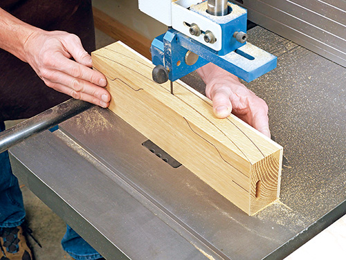
Head to the band saw so you can cut the rails’ curved profiles. Carefully cut just outside the curved layout lines, and make these long curved cuts in a single pass. After you cut each waste piece free, stick the offcut back into place on the blank with pieces of double-sided tape before cutting the second long curve. This way, the blank will retain most of its original thickness so it can stand squarely on the saw table for safer and more accurate cutting now, as well as during routing in the next step.
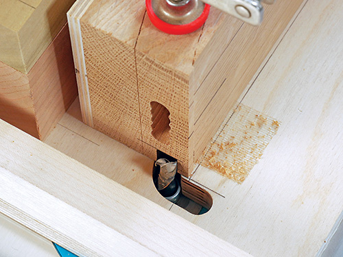
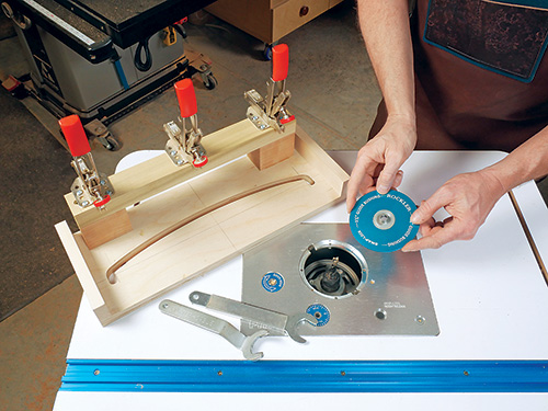
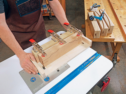
Notice in the Drawings that the crest and back rails have a long curved groove that houses the chair’s back slats. We’ll rout these grooves into the rails now. This would be a tricky and nearly impossible operation for a handheld router to accomplish, but it’s quite easy to do with a purpose-made jig at the router table. The jig I made consists of a 3/4″-thick plywood base with a 1/2″-wide groove routed through it that matches the curves of the crest/back rail. Three clamps on the jig press the rail workpieces down during routing, and I added a couple of strips of double-sided tape to the jig base for even more insurance. To use the jig, I install a 1/2″ O.D. guide collar and a 3/8″ upcut spiral bit in the router table. The guide collar’s bushing fits inside the jig’s groove. Sliding the jig from side to side routs the curved grooves consistently and easily.
To create the curved groove in the jig’s base, I used my MDF crest/back rail template to create a much larger template with a curved edge that was wide enough to support the base of a handheld router. With a 1/2″ spiral upcut bit installed in the router and a guide collar surrounding the bit that was just large enough for bit clearance, I attached my larger curved template to the plywood blank for the jig base and template-routed completely through it to form the jig’s slotted opening. Keep the router pressed firmly against the larger template as you rout your way through the jig base — the smoothness and accuracy of this groove determines how well the jig will work for routing the grooves in the chair rails.
Assemble the jig and use it to mill a centered, 3/8″-wide, 1/2″-deep slot along the bottom edge of the crest rail and into the top edge of the back rail. Be sure to center the crest and back rails carefully on the routing jig when clamping them to ensure that the grooves will be positioned accurately. Rout these grooves in a series of three or four deepening passes.
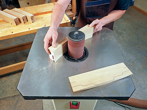
It’s time to sand the curved faces of the crest and back rails, so take them to your spindle sander or use long sanding drums on a drill press. When you remove the taped offcut to sand each face, stick it back on after sanding to help stabilize the workpiece for sanding the other face. If you have neither machine option for this step, a flexible sanding block will also do the job.
Once that’s done, go ahead and cut the top cloud lift profile to shape on the crest rail. Do this with both front and back waste pieces taped in place. Sand this profile smooth before removing the front and back waste pieces for the last time.
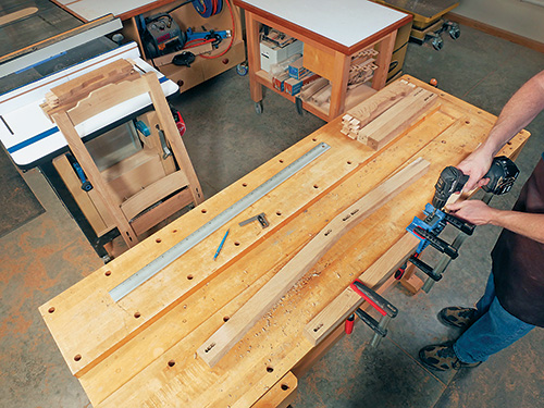
Next, mark the inside faces of the back legs for the four Beadlock mortises that will attach the crest and back rails to them. Locate centerlines for the crest rail mortises 1-1⁄4″ down from the top ends of the back legs, and mark the centers of the back rail mortises 22″ down from the legs’ top ends. To drill these 1-1⁄4″-deep mortises, install the 1/2″ spacer behind the guide block in the Beadlock jig, and clamp the jig to the front faces of the back legs this time. (The crook in the back legs doesn’t allow the jig to be clamped properly for drilling the back rail mortises; that’s the reason for using the front faces of the back legs to register the jig.)
Cut 2″-long Beadlock tenons for the crest and back rail joints, then dry fit these rails in the chair framework with the tenons in place to confirm that the parts go together well.
Creating the Thin Bottom Rails
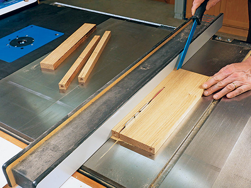
The two bottom rails and cross rail are 7/8″ x 7/8″ in section, and they’ll be joined together and to the chair legs with 3/8″-dia. dowels. It will be difficult to clamp most doweling jigs to the ends of rails this thin to drill centered holes into them. So start with a piece of 7/8″-thick, 14-1/2″-long stock that’s much wider than necessary to create the two bottom rails. Mark center points for drilling that are 7/16″ in from both long edges of your workpiece, and clamp your doweling jig securely to drill 3/8″-dia. holes 3/4″ deep. Then take the workpiece to your table saw and rip both 7/8″-wide rails from it. Make these cuts carefully to be certain the dowel holes are centered on the rail ends.
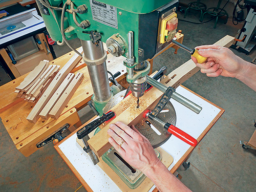
Now drill a 3/8″-dia., 3/4″-deep hole into each bottom rail for the cross rail. Center these holes, lengthwise.
Study the Drawings to verify the correct faces of your chair legs for marking the dowel hole locations for the bottom side rails. These dowel holes should be 8-1/2″ up from the bottom end and 15/16″ in from the outside face of each leg (this will locate the bottom rails 1/2″ in from the outside leg faces). Once you’ve marked the four center points, head to the drill press so you can drill them 3/4″ in deep with a brad-point bit.
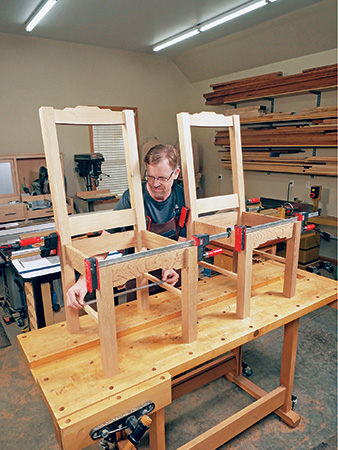
With that done, dry fit all the chair parts together up to this point with the Beadlock tenons and dowels in place, and clamp the joints. This will help you determine what the final length of the bottom cross rail should be. Make it the same way as you made the two other bottom rails, starting from a piece of wider stock and drilling the dowel holes into its ends before ripping the cross rail free. Test its fit between the bottom rails in the chair with the tenons and dowels fitted into place.
It’s finally time to take the front legs to the band saw and rough cut their front cloud lifted faces. Template-rout these profiles to final shape, then sand the legs’ front faces smooth using an oscillating spindle sander, sanding drums or by hand sanding.
Installing Back Slats, Spacers
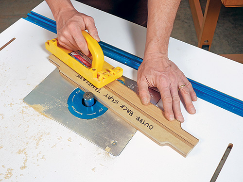
It’s time to get those back slats into place! So dry assemble the chair again in order to measure the actual distance between the back and crest rails from the bottom of the curved grooves. Then prepare enough 3/8″-thick stock to rip the six straight slats to size. Rockler’s cardboard template kit provides a template for the two curved outer slats, or use our gridded drawing. Trace their shapes on a workpiece that’s wide enough to create both slats. Saw the profiles just outside the layout lines, and sand or template-rout the cloud lifts smooth and even. Rip the outer slats free. Sand all eight slats up to 180-grit.
Despite the fact that the slat grooves in the crest and back rails are curved, the spacers that fit between the slats and hold them in position can actually be made from straight strips of stock, because the curvature of the grooves is so gradual. Prepare long strips of 3/8″-thick, 1/2″-wide stock. The 18″ length that’s specified on the Material List is longer than necessary to allow for a few extra spacers, if needed.
Carefully cut two 1-1/4″-long spacers to fit between the center two slats and a dozen 3/4″-long spacers that fit between the rest of the straight-edged slats.
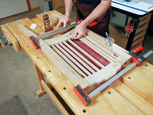
Finish sand the crest and back rails and the slats, because we’ll be installing the slats and spacers permanently at this point. When those are smooth and ready to go, dry fit all eight slats between the two rails in the grooves, and reinstall this loose assembly back on the chair. Spread the slats out along the grooves so they’re roughly in position. Then, starting in the middle of the crest and back rails, insert the two 1-1/4″ spacers with dabs of glue into the rail grooves. Double-check that these two spacers are centered on the rail lengths. Slide the adjacent pair of slats against these longer spacers. Now glue and insert 3/4″-long spacers into the grooves alongside the first two slats. Slide the next slats over, and repeat this process to position and locate the other straight slats, 3/4″ spacers and the outer two profiled slats.
The outermost four spacers that fit between the profiled slats and the back legs should be about 1-3/8″ long, and you’ll need to trim their ends at angles to fit flush against the legs. It’s a fussy process, but take your time to get a good fit. Once these four spacers are ready, glue them into place in the grooves to finish the slat installation. Let the glue dry while the backrest subassembly is still dry fitted on the chair.
Assembling the Framework
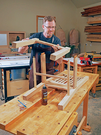
Take the chair apart so you can finish sand all the faces and edges of the legs and rails to 180-grit. I also used a sanding block to break all the sharp edges of the parts to reduce the chances for splinters and to give the chair a softer-looking appeal. Chamfer the top and bottom ends of the back legs and the bottoms of the front legs with a trim router and chamfering bit set for a 1/8″-deep cut. I think chamfering the bottom ends of furniture legs is always a good idea — it safeguards these fragile edges and corners from chipping during use.
With that done, you can start the final assembly process by gluing and clamping the backrest subassembly and back seat rail between the two back legs with Beadlock tenons installed. Then glue and clamp the front seat rail and front legs together with their tenons in place. Assemble the lower rails and cross rail with dowels and glue, making sure that this “H” configuration of parts lays flat on a work surface. I used hide glue for all of these connections because we’ll be staining these chairs, and any glue splotches I might have left behind — which stick out like a sore thumb under a stained finish — are easy to clean away by scrubbing with water.
When the back, front and bottom rail subassemblies dry, bring the whole chair frame together by adding the side seat rails and lower rail assembly with their tenons and dowels in place.
Adding the Seat Board and Finish
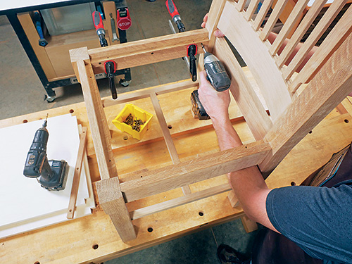
The upholstered seat consists of a 3/4″ plywood seat board with a layer of 2″-thick foam on top, covered with your choice of fabric, vinyl or leather. The seat board rests on four cleats. Make the seat board by measuring its opening on your chair frame — it may vary slightly from the Material List size. Make the seat board about 1/8″ smaller in both dimensions than its opening in the chair frame, in order to fit the seat covering you have in mind. Whatever covering you choose, it will need to wrap around the edges of the seat board and will take up the extra space inside the frame. Cut the seat board to shape, then mark and cut a 3/4″ x 3/4″ notch out of each corner at the band saw or with a jigsaw so it can fit around the inside corners of the chair legs.
Sort through your project’s scrap lumber for a piece to make the chair’s four seat board cleats, and rip and crosscut those to size. Make the thickness of these cleats match the distance from the inside corners of the legs to the seat rails; on my chair, it’s 11/16″. Position and clamp the cleats against the seat rails inside the chair framework so the top of the seat board will be flush with the tops of the front legs and seat rails. Fasten the cleats to the seat rails with three countersunk screws per cleat.
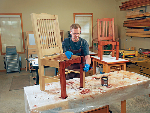
Old Master’s Red Mahogany oil-based stain enriched the color of the white oak I used for my chairs. It also will match the color of the Cloud Lift Table that ran in our June issue, if you’re planning to use these chairs as a set with that table. Mix the stain well and wipe it onto all the exposed wood. Allow the stain to absorb for a few minutes, then wipe off the excess. Give oil-based stain at least 24 hours to dry thoroughly. Longer is even better, especially if your shop is humid or cool.
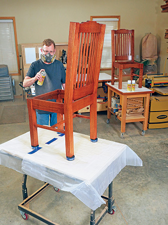
The next day, you can topcoat the chairs with your choice of finish. I started by spraying on two light coats of clear aerosol shellac to enhance the oak’s quartersawn figure and to help build a film of finish quickly. When that dried, I followed with aerosol lacquer to change the finish from shellac’s low glossiness to a duller satiny sheen.
Simple Upholstery Wraps It Up
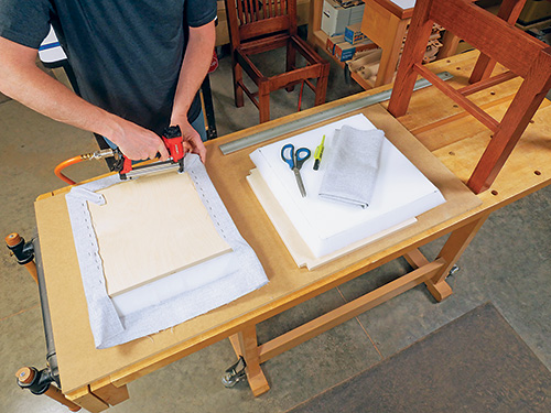
Upholstering the square seat boards of these chairs is about as easy as that job can be. Start by breaking their sharp corners with a file or sanding block, then skim off the long top and bottom edges as well as the sharp areas in the notched corners with a 1/8″ roundover bit in a handheld router. Doing this will prevent tearing the fabric when you’re stretching it over the seat board, and soft edges will also prolong the life of the fabric over time. Then draw four layout lines on one face of the seat boards, 2″ in from each edge, to create a smaller penciled square layout area.
Ordinary 2″-thick, high-density urethane foam, available at fabric stores, is a good thickness and choice for padding. Mark one face of the foam with a 15-3/4″ square — or to match the actual size of your seat boards. You can certainly cut this foam with a long-bladed, sharp utility knife, but a band saw will do the job even better. Tip the saw table to 30 degrees, and carefully cut along the layout lines you’ve marked on the foam to create a beveled seat pad with its angled edges flaring out from your marked lines (the face opposite the one you marked will end up being a larger square after it’s bevel-cut to size).
Cut your fabric or other seat covering to 23″ x 23″. Lay it face down on a work surface and center the beveled foam on it with the larger face of the foam against the seat covering. Set the seat board on top of the foam with its pencil-marked face up and the edges aligned with the foam’s edges. Now gently pull the side flaps of the seat covering up and over the seat board, one side at a time, and staple the flap to the seat board. Pull the covering evenly, aligning its edge to the penciled layout line you drew on the seat board earlier. A helper can make this holding-and-fastening process easier to do.
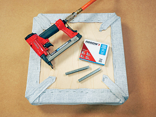
When stapling, drive a staple in the center of the flap first, then work your way out from there, pulling the covering evenly and stapling every 2″ or so. Now pull the remaining unstapled areas of seat covering taut, and drive more staples to hold these areas in place, too.
I quickly discovered that while a manual staple gun might be up to task for this operation, mine sure wasn’t. The Baltic birch I used for my seat boards just bent the staples. So I switched to a PT50 pneumatic stapler from Arrow, which was both inexpensive — around $40 at a local home center — and worked like a charm to sink the staples properly.
When all four flaps are secured, pull the four corners of the seat covering up and over the seat board notches to form long tongues. Staple these tongues down securely.
Press the upholstered seat board down into place in the chair frame, and drive 1-1/2″ wood screws up through the cleats to attach the seat. These new dining room chairs are now ready to use — and you can add them to your proud list of woodworking accomplishments!
