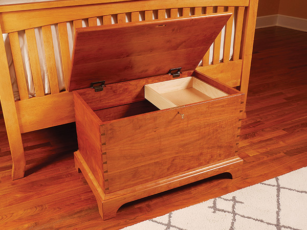
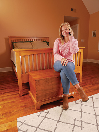
Whether you use this moderately sized chest for storing bedding, photo albums and other keepsakes or off-season clothing, it’s also just the right height to serve as a quick seat for putting on your slippers or shoes.
I think every woodworker should eventually build a Shaker-inspired chest like this, because it’s one of those enduring woodworking classics. It also provides a good opportunity to practice your dovetailing skills. If you haven’t built a chest like this before, here’s your chance to give one a go!
Starting Out with Dovetails
Let’s get this project underway by gluing up panels for the chest’s front, back and sides. Flatten their glue seams by scraping or hand-planing, sand the panels up to 120-grit and then cut them to final size, making sure their ends are square. Mark the outside “show” faces on the panels, and label the corner joints to keep their orientation clear.
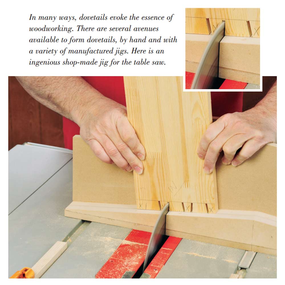
The next step is to cut through dovetail joints to bring the chest panels together. You could cut these with a router and dovetail jig, which is a perfectly acceptable option. But for this project, I wanted to make narrower pins than my dovetail jig will allow. I also wanted the freedom to space the pattern as I liked, so I decided to cut them by hand instead.
If you like the look of my pin and tail pattern (see the Drawings), lay out the tails on the front panel. Start by scribing a baseline for the tails all the way around both ends of the panel with a marking gauge. Set these scribe lines about 1/32″ deeper than the thickness of the side panels (this way, the tails will protrude ever so slightly when the joints are assembled so you can trim or sand them perfectly flush).
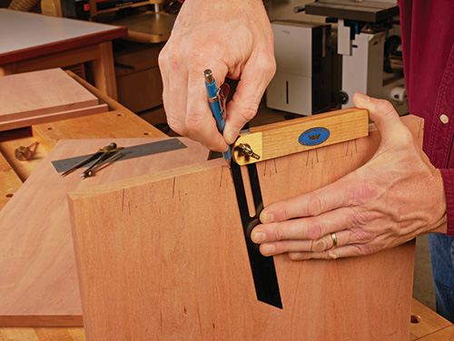
Then lay out the centerpoints of the pins, with a half pin on the top end of the chest only. I laid mine out with eight pins, spaced 1-7/8″ apart, on center. The bottoms of the pin sockets are 1/2″ wide, and I set the angles of the tails to a 1:6 slope (about 10°). Use a sliding bevel to draw the tails to shape with a sharp, fine-point or mechanical pencil.
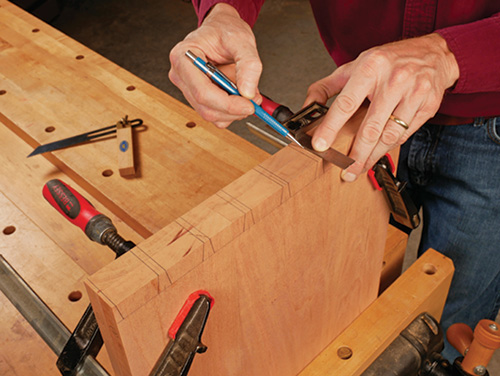
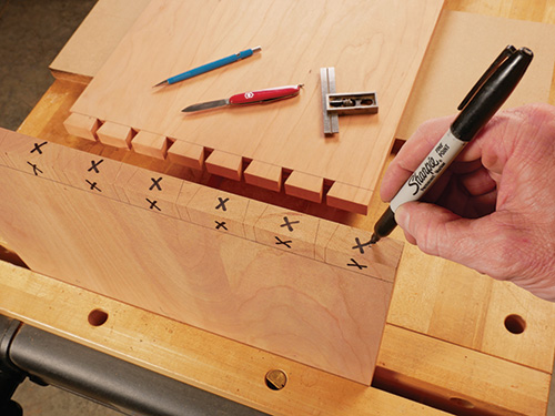
Extend the tail reference lines across the ends of the front panel with a square. Scribe baselines for the tails onto the back panel. Then clamp the back panel to the front panel with their inside faces against one another and so the ends and edges are even. Transfer the tail lines from the front panel to the back panel. Use these lines as references to draw a matching pattern of tails on the outside face of the back panel.
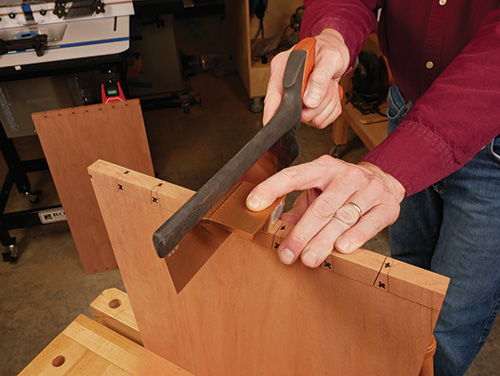
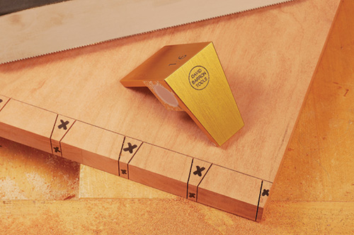
Next, saw the tails down to the baselines with a fine-toothed dovetail saw, following your layout lines. If you’re skilled with handsawing, you’ll do these freehand. But, if you’re less than confident that you can saw squarely and accurately, I tried out a clever and simple one-piece aluminum jig that I’ll highly recommend to you.
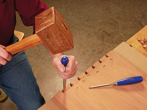
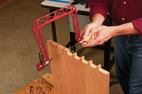
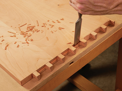
Once the tail cuts are made, remove the waste between them to create the pin sockets. You could chop the waste out with a 1/2″ chisel, working in from both faces of the panels and down to the base lines. Or, you can saw it out with a coping or fret saw first, leaving just a bit of waste at the bottom of each pin socket. Then, pare or chop this waste away, working carefully and in from both faces. When the sockets are cleaned out, make sure their baselines are flat across the panel thickness so the pins will slide into them squarely. Check the baselines with the blade of a square extended through the sockets; it should rest evenly across them. Then, carefully trim off the half-pin waste on the top end of the panels.
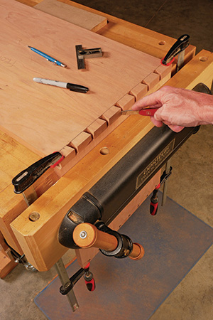
With the tails now cut to shape on both the front and back panels, clamp a side panel to the edge of your bench with an end facing up, and align the correct tail board over it. Carefully transfer the angled tail pattern onto its end to mark for the pins. Use a sharp, thin-bladed pocketknife or a marking knife to scribe these lines. Repeat for the other three corner joints.
Grab your marking gauge, again set 1/32″ deeper than the thickness of the front and back panel, to scribe baselines across the faces of the side panels so the pins will protrude slightly beyond when the joints are assembled. Darken the knifed pin lines with a sharp pencil to make them easier to see when sawing. Then draw straight lines down from the knifed lines on the end grain to the baselines to complete the pin shapes.
With each side panel clamped at a comfortable working height for hand-sawing, cut straight down to the baselines to form the angled faces of the pins. Again, my Barron Dovetail Guide, flipped to its pin orientation and held in place, was able to help me guide these cuts easily. Aim as best you can to literally split these layout lines with the saw blade — it will help to minimize the amount of paring you’ll have to do next to refine the fit of the joints.
Saw or chop out the waste in the tail socket areas. Effectively, the process is the same as when clearing the pin socket areas, but here there’s more waste to remove. Use wider chisels to help speed the process along, and work carefully when you’re chiseling up to the baselines to keep them straight and evenly aligned with one another. The scored baselines will give your chisel edge accurate registration here.
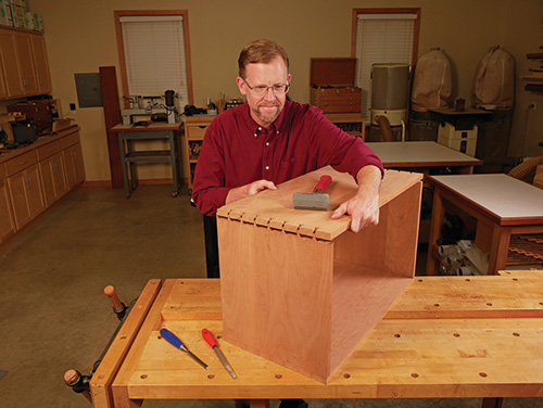
Now, fit the corner joints together one joint at a time. If you’ve cut carefully, the pins and tails should engage one another at least partially, right from the start. If they don’t, you’ve got some paring to do to improve the fit. The important point of note here is to pare as little material away as possible so the joints will close snugly. Remove too much, and you’ll open up gaps that will show. Remove too little, and the panels can crack if it takes excessive force to engage the dovetails. Pare only from the angled, inside faces of the pins, leaving the tail pattern alone. Work slowly and carefully. Continue to test-fit the joints until they close easily enough to tap together by hand without undue force.
Forming Rabbets and Grooves
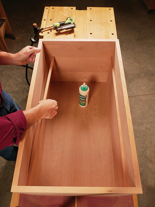
Notice in the Drawings that the chest’s bottom panel fits into a 3/4″-wide, 3/8″-deep rabbet that runs around the bottom inside edge of the chest. Each of these rabbet cuts must stop before it reaches the ends of the panels, or the cuts will show through when the dovetails are assembled. With the chest carcass dry-fitted together, mark out the rabbeted areas.
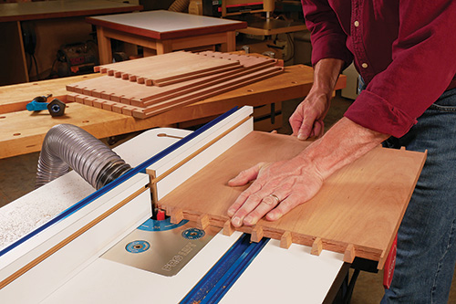
I used a 3/4″-dia. straight bit in a router table to mill these rabbets in a series of progressively deeper passes. Make sure to mark the cutting limits of the bit on your router table’s fence so you’ll know where to start and stop these cuts. Square up the rounded ends of the rabbets with a sharp chisel.
And since you’re at the router table, there’s also a 1/2″-wide x 1/8″-deep groove that runs along the inside faces of the front and back panels to fit two cleats that will support the chest’s movable tray. Rout these two grooves now as well. I terminated the grooves 1/4″ from the ends of the panels.
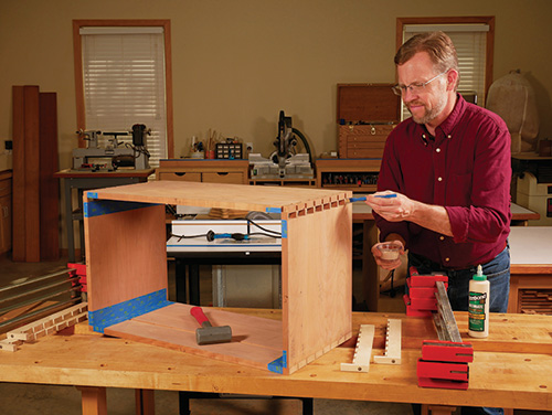
Finish-sand the inside faces of all four chest panels up to 180-grit. Now go ahead and assemble the chest carcass with glue and clamps, making sure the box is square by measuring across its diagonals. Don’t rush the job — I glued up the back corner joints in one session with the front panel dry-fitted as a spacer. Then, when those joints dried, I glued the front corner joints together. Once the carcass comes out of the clamps, clean up the outside faces of the corner joints by planing or sanding until the ends of the tails and pins are flush.
Cut a 16-3/4″ x 29-1/4″ plywood bottom panel to fit the chest’s rabbeted recess. Sand the inside face of the plywood smooth. Then glue and brad-nail the panel into place. Make up some tray cleats, too, and install them into their grooves in the front and back panels.
Building the Base
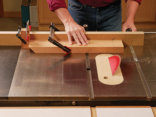
The chest’s base consists of four 1-1/2″-thick workpieces, beveled to 45° on their ends. Start out by ripping them to a final width of 4-1/4″ and crosscutting them overly long by a few inches. Bevel joints are invariably tricky to cut accurately so they close tightly, and the wider the joints or thicker the material, the more exacting your saw setup needs to be. I made a long scrap fence of doubled-up MDF and attached it to two miter gauges in order to provide plenty of stout backup support for these long workpieces. I also used a 1/8″ full-kerf blade on my table saw — the thicker and stiffer the blade, the flatter the cuts will be. However you choose to make these angled cuts, test your saw setup by making practice cuts first and adjusting the blade’s tilt angle as needed until the joints meet at 90°. Then, bevel-cut the parts to final length, using a stop block and clamps to control the part lengths accurately.
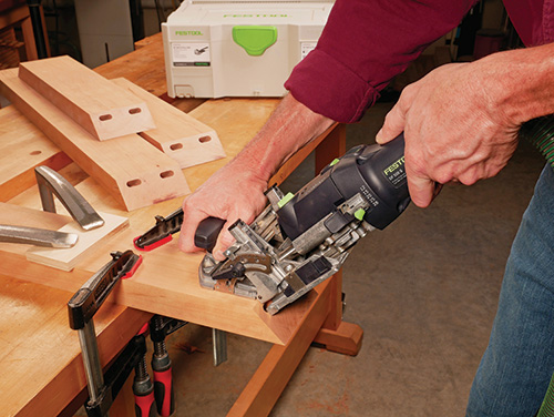
Glue alone won’t offer enough strength on these end-grain joints, so I reinforced them with two 10 x 50 mm Festool Domino tenons at each joint. Dowels, biscuits, short splines or shop-made loose tenons would be good options here if you don’t have a Domino joiner. Dry-fit the base together with these reinforcements in place so you know the joints will close completely.
Next, it’s time to cut the base’s curved feet. I made a pair of scrap plywood templates — one for the cutout on the base’s front and back and another for the base sides. I used them first as tracing guides and rough-cut the feet to shape at the band saw. Then, I adhered the templates to each workpiece with carpet tape in order to trim the contours to final shape with a long piloted flush-trim bit at the router table.
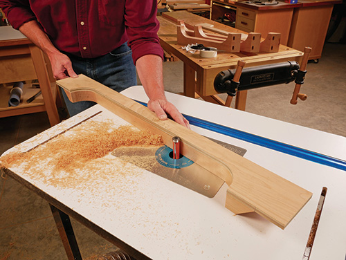
Sand these curves and the rest of the part surfaces up to 180 grit, and glue the base together. Use strap or bar clamps to pull the joints tight.
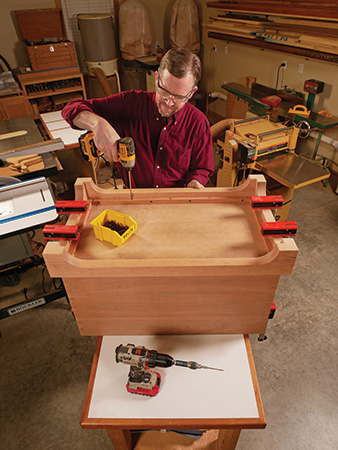
Give the base joints several hours to dry, then go ahead and fasten the chest carcass and base together. Do this by attaching 3/4″ x 3/4″ cleats to the inside faces of the base with countersunk screws. Position the top edges of the cleats flush with the top edges of the base. The base projects 1″ out from the chest carcass all around; invert the chest carcass and position the base over it carefully. Clamp the carcass and base together, then drive countersunk attachment screws through the cleats and into the chest bottom.
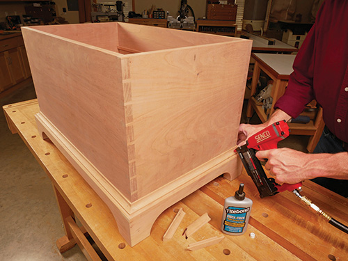
All that’s left to do on the base is to make and install moldings around its top edges to create a pleasing visual transition here. I chose a 5/8″-radius cove profile for my moldings and milled it into 3/4″ x 3/4″ strips of leftover cherry at the router table. Finish-sand the moldings, miter-cut them to length, and install them — it’s a good idea to cut and fit these pieces one at a time so you can make any necessary adjustments to the joints as you go.
Mounting the Lid
The chest’s solid panel lid overhangs the carcass by 3/4″ all around. In back, the overhang helps to hide the large torsion hinges from Rockler that I used for this project (they hold the lid open through much of its travel without further support and prevent it from slamming down). Glue up the lid panel, and flatten the glue joints when it comes out of the clamps. Then, cut it to final width and length.
Locating these non-mortising hinges accurately on the lid is a bit of a “blind” operation if you mount them to the carcass first. That’s because they’re inset from the lid’s back edge and don’t benefit from the registration advantage that mortises would offer. So, to make things easier, I started by mounting the hinges to the lid instead of to the carcass back. That way, there’s no guesswork about where the hinges should then be attached to the lid. If you do the same, make sure the hinges are perfectly aligned along a penciled layout line when you screw them to the lid. I spaced them 4-3/4″ in from the ends of the lid and positioned the front edge of their hinge leaves 2-1/4″ in from the lid’s back edge.
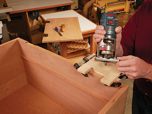
With the hinges in place, set the lid on the chest and mark the carcass back for the hinge locations. When closed, these hinges are about 3/16″ thick, which will prevent the lid from resting completely flat on the chest. I didn’t want to see a gap under the lid, just because of the hinge thickness, so I cut a pair of wide mortises into the top back edge of the carcass to recess the hinge bodies. A trim router, shallow piloted mortising bit and a simple edge guide made it easy to do this accurately.
Install the hinge leaves into the chest mortises with a few screws so you can test the lid’s fit and hinge action. If you’re satisfied with the result, remove the hinges from both the chest and lid so you can add a decorative profile to the lid’s front and side edges. I shaped the bottom edges with a 3/8″-radius piloted roundover bit to complement the cove molding on the base and to make the lid more pleasant to grasp. Along the lid’s back, I just eased the sharp edges and corners with a sanding block and left it at that.
Adding the Sliding Tray
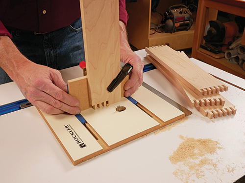
The tray is simply an open-topped box with a 1/4″ plywood bottom that gives this chest a second level of internal storage. I made mine from 1/2″ maple, which provides a splash of brighter wood color to the rest of this project’s dark cherry. Once its front, back and sides were cut to size, I brought the corners of the tray together with 1/4″ box joints to add some decorative flair and strength. Be careful to stop the bottom panel grooves accordingly when you rout them so they won’t show through on the assembled joints. I positioned these grooves 1/4″ up from the bottom edges of the tray framework. Sand the tray parts, and glue it together.
Final Hardware and Finishing
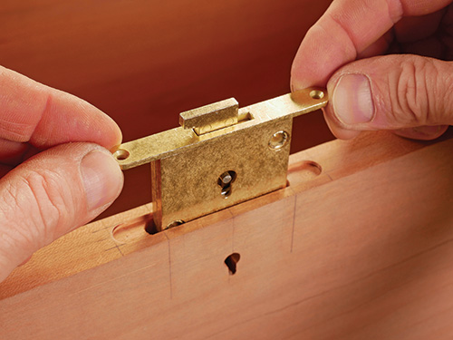
To give this chest a bit of security, I added a keyed lockset. Rockler provides a step-by-step instructions page for installing it, which is available as a downloadable PDF. But briefly, here’s how the process goes. I centered the lock on the chest’s front wall, then bored a 1-1/2″-deep, 1-7/8″-long mortise for the lock body using a 5/16″-dia. brad point bit and a clamp-on doweling jig.
The lock has a 3/8″-wide, oblong selvedge plate on top that requires a shallow mortise to recess it into. I routed that mortise with a shop-made, clamp-on slotted jig, 3/4″ O.D. guide collar and a 3/8″ straight bit. Once the selvedge mortise was cut, I switched to a long 5/16″-dia. straight bit and, using the same shop-made jig, cleaned up the walls of the deep mortise. But, a chisel would do the job just fine, too.
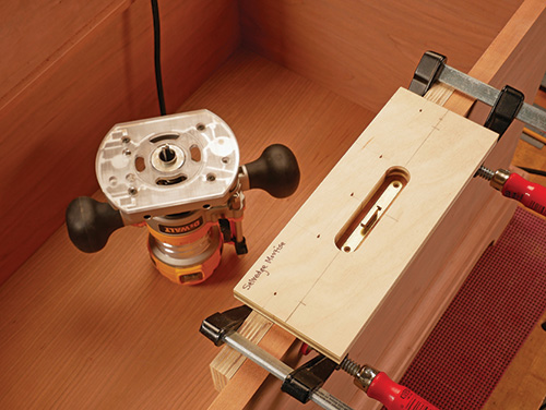
A 1/4″-dia. hole, drilled through the face of the chest, and a little chiseling below that, provided access to the lock for the skeleton key. Install the lock body in the chest with screws.
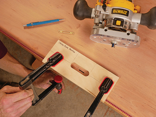
A brass strike plate attaches to the chest lid to engage the lock bolt. Mark the underside of the lid carefully to position this strike plate — you only have one shot to get it right! I knew I was on target by using a simple trick: I colored the top edge of the raised lock bolt with a black permanent marker and closed the lid down onto it to transfer the bolt’s exact location. Another shop-made jig with a shorter slot helped me rout the strike plate mortise accurately. The bolt also requires extra clearance behind the strike plate so it can pivot up into the locked position. For that, I switched to a 3/16″-dia. straight bit and used the same mortising jig to excavate the bolt’s deeper recess. Attach the strike plate to the lid to wrap up the hardware installation. Then remove the lock components and hinges to prepare for finishing.
A good way to warm up the color of cherry and accentuate its figure is to apply a drying oil first. I wiped on a heavy coat of Rockler’s 100 percent pure tung oil and gave that a full 24 hours to dry, followed by a barrier coat of dewaxed shellac to seal in any oily residue and smell, then four coats of satin lacquer.
To keep the maple tray as blonde as possible, I used a water-based non-yellowing varnish from General Finishes called High Performance. It dries incredibly fast and imparts very little color to the wood. My hope is that, whenever this chest is unlocked and opened, the lighter-colored tray with its showy corner geometry will be a welcomed surprise waiting inside.
Click Here to Download the Drawings and Materials List.
Hard to Find Hardware
Lid-Stay Torsion Hinge Lid Support, Rustic Bronze (1) #37327
Full Mortise Chest Lock (1) #28241
