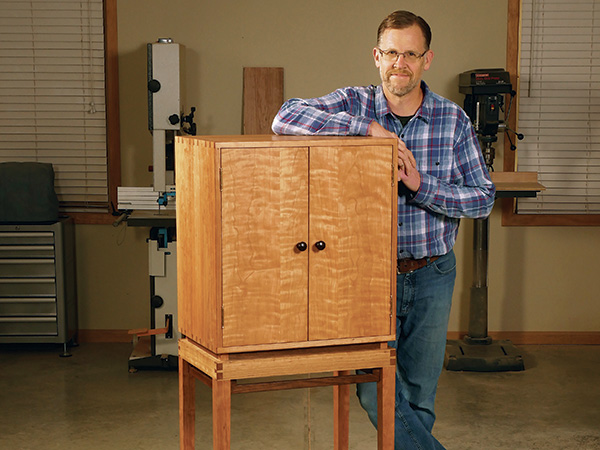
James Krenov’s distinctive cabinets, elevated on long-legged bases, have inspired scores of woodworkers to imitate similar forms. I’m one of them! So when the opportunity finally came to build a cherry cabinet on legs, I jumped at the chance. Our art director Jeff Jacobson drafted the overall concept, including the unusual frame-within-a-frame apron design of the leg base. If you look closely, four inner walnut frames set behind a “belt” of dovetailed cherry outer aprons. It’s a light and dark peek-a-boo effect that definitely catches the eye! These walnut frames and the tops of the leg tenons also protrude above the aprons, to suggest a sense of lightness, as though the cabinet is lifting off its base.
Making the Aprons and Legs
Take a few minutes to study the leg base drawings. One thing I didn’t mention already is that the interface between the inner and outer frameworks will involve some close tolerances, because the outer dovetailed apron assembly effectively “captures” the inner walnut framework. These inner frames also connect to the legs’ offset upper tenons with tongue-and-groove joints. It’s precision work, to be sure.
We’ll join the four aprons together first, then machine the legs and their tenons so we can be certain of the fi nal part lengths for the inner frames’ rails. So start by preparing four blanks for the front, back and side aprons. Make up a set of full-size test pieces for these parts too, from scrap stock.
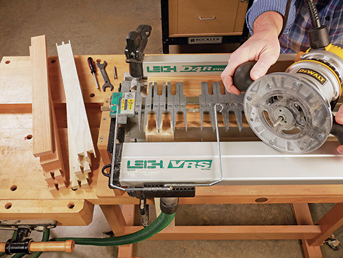
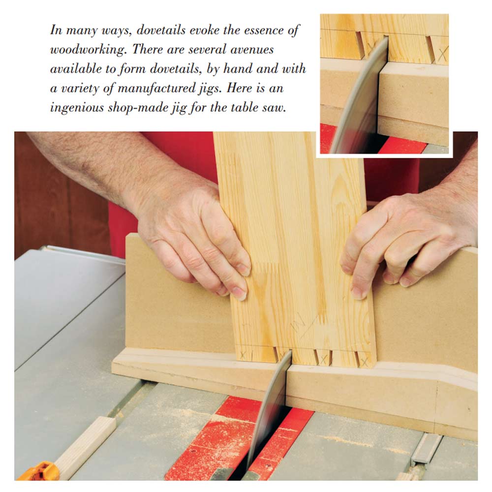
Set up your dovetail jig to mill through dovetail joints. The Leigh D4R Pro jig that I used can produce variable-spaced dovetail patterns, which adds a customized detail to the joinery. You can see the layout I followed for spacing the tails on the ends of the side aprons in the drawing. If your jig isn’t able to create variable-spaced dovetails, you could rout a regular pattern of tails and pins instead. They’ll work fine.
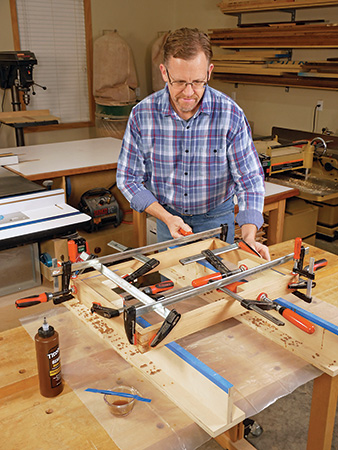
Mill dovetails into your apron test pieces and refine your dovetail jig setup until they fit together with light pressure. When they do, machine the dovetails on the actual apron parts. Final-sand the aprons up to 180-grit, and glue them together. Squareness of this assembly is critical, so be careful about where and how tightly you position your clamps.
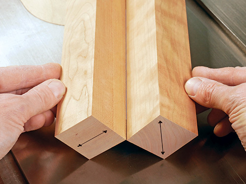
Next, prepare four blanks for the legs as well as a test piece from 8/4 solid stock so you can dial in your joinery and taper cuts. Surface these parts to 1-3⁄4″ square, and mark their ends to keep their orientation clear. I chose to cut my leg stock from riftsawn portions of my lumber for a more consistent grain pattern on all four faces.
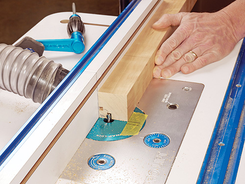
The leg base’s walnut inner frames will have continuous tongues on their ends that fit into matching grooves on the legs. So we’ll begin by cutting the leg grooves. Install a 1/4″-diameter straight or spiral bit in your router table, and set the fence 1/2″ from the closest edge of the bit.
Lay out the positions of a pair of 1/4″-wide, 5-1/4″-long grooves on the legs. These grooves are located 1/2″ back from the inside corner of each leg on adjacent faces. Then make two reference marks on your router table that indicate the cutting limits of the straight or spiral bit so you’ll know where to start and stop these groove cuts.
Rout the leg grooves into a test piece. Make each groove cut in several passes of increasing depth until they’re 3/8″ deep. When I routed these pairs of grooves, I cut in from the top end of the leg for one groove but switched to a “drop cut” (starting at the closed end of the groove and cutting outward to the end of the leg) for the other groove. Doing this enabled me to keep the same fence setup for the entire milling operation. If you’re satisfied with the groove cutting results on your test piece, repeat the process on the actual leg blanks. Then chisel the bottom ends of the grooves square.
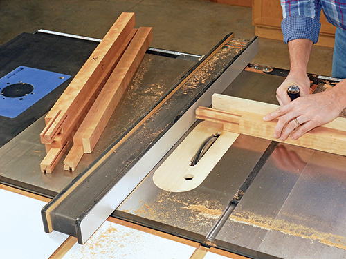
With the grooves milled, it’s time to raise 1″-square x 3-1/4″- long offset tenons on the top ends of the leg test piece and the actual legs. I cut these at the table saw with a wide dado blade raised to a cutting height of 3/4″. Keep your concentration focused when forming the cheeks and shoulders of these tenons to avoid mistakes: you are cutting away material only on the faces without groove cuts. Don’t get confused. The two inside (grooved) faces of the legs are tapered. These tapers begin 5-1⁄4″ down from the top ends and reduce the legs to 1-1/4″ square at their bottom ends. Lay out and cut both tapers on your leg test piece first before committing to the actual leg blanks. Be very careful when making these taper cuts as well; they can be confusing, considering the unusual placement of the offset tenons. Mark them clearly so you can visually confirm each cut before making it.
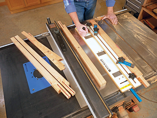
When the dust clears from that operation, smooth the tapered faces and remove any sawing marks with a sharp hand plane or by sanding. Chamfer the bottom ends of the legs to help safeguard against splintering down the road, and ease the long, sharp edges of the legs slightly with a sanding block.
Assembling the Leg Base
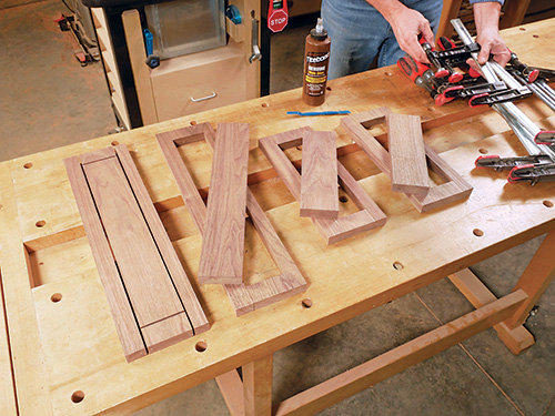
Position and clamp the four legs against the inside corners of the assembled apron with the apron resting on the tenons’ shoulders. Now measure the distance between the bottoms of the groove cuts so you can determine the overall length of the top and bottom rails we’ll build next for the leg base’s internal frames. Add 1/16″ to these long (front, back) and short (side) rail measurements. That way, you’ll be able to shorten them a little at a time for a perfect final fit.
The inner frames could be made conventionally with four sticks of long-grain material each, like a cabinet door. But in this case, those frames would come together at the corners without reinforced joinery — only weak, cross-grain butt joints. So I decided to make my frames by cutting the rails from long-grain material and the stiles from short-grain material of the same board sections. I started with 7/8″-thick, overly wide boards cut to the final rail lengths as determined in the previous step. I ripped a 3″-wide strip from each board’s center, first, then ripped the top and bottom rails from the pieces that straddled these center portions. I crosscut the stiles from the ends of the center piece. With this strategy, each frame has continuous, matching grain with an opening that appears as though it was simply cut out of the middle of a board. It also allows the corner joints to be long-grain connections — a much stronger gluing solution than cross-grain.
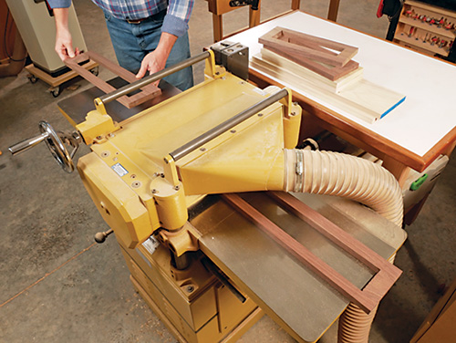
Carefully glue the rails and stiles together to form the four long and short inner frames. I used hide glue for this operation, because the excess can be removed with water and a little scrubbing after it cures. That’s a handy benefit when cleaning out their inside corners, especially when half of each inside corner joint is end grain that wicks up glue, which is notoriously hard to clean away. Once the glue dries, surface the inner frames down to 3/4″ thick. While you’re at it, prepare a test piece for each inner frame. These will be helpful in refining the final inner frame joints and part lengths.
Go ahead and glue and clamp the legs into place within the apron. When the clamps come off, sand the legs and outer surfaces of the apron assembly up to 180-grit. Now it’s time to fit the inner frames in their grooves. The ends of the frames require 1/4″-thick, 3/8″-long tongues to fit into the leg grooves. So set up your table saw with a wide dado blade, and make a tongue on one end of one scrap piece. See if it fits the leg grooves, and raise or lower the blade slightly as needed to improve the fit. You want the tongues to be snug but not tight.
When you have the tongue-cutting blade setup dialed in, head to your miter saw to crosscut the four test frame pieces to the correct length for each of the long and short frames. Be advised that the lengths may vary by fractions of an inch for each frame, depending on the accuracy with which you’ve made the legs and aprons up to this point. But that’s the advantage of making a test piece for each frame.
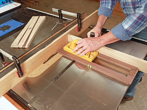
Now raise tongues on the ends of the test frame workpieces and check that they seat properly in their grooves. If they do, mill tongues on the actual frames and dry fit them. Make sure the top rail edges align with the top ends of the leg tenons to form a flat top surface for supporting the upper cabinet.
Give the frames a final sanding. I stained them with Watco Dark Walnut oil/varnish blend to warm up the walnut’s grayish and purplish undertones. When the finish cured, I spread glue into the grooves and fit the frames into place on the base.
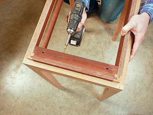
The base still needs a means of connection to the upper cabinet. My solution was a pair of 1″-thick, 1-1⁄2″-wide cleats attached to the upper rails of the inner frames. Before installing them, I drilled a round center screw hole and machined two slotted outer holes for attaching the cabinet, to account for its inevitable cross-grain, front-to-back wood movement.
Building the Dovetailed Cabinet
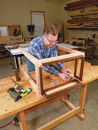
With the leg base’s construction completed, glue up panels for the cabinet’s top, bottom and sides, plus a spare panel or two that you can use as setup aids for adjusting your dovetail jig. When the panels come out of the clamps, sand them smooth and flush, and trim them to final size.
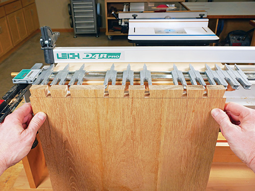
As I mentioned earlier, my Leigh D4R Pro Dovetail jig has an adjustable guide finger assembly that allows through dovetail patterns to be spaced variably. I tried out a couple of tail pattern options on a piece of scrap to settle on a custom pattern that I liked. The only way to truly see what the effect will be is to rout a sample piece, so it’s worth the effort.
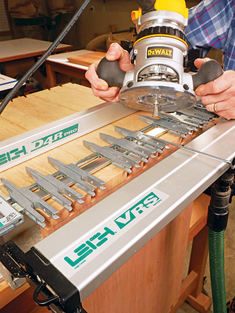
The D4R Pro requires that the tails of a through dovetail joint be routed first, then the pin boards are routed and the jig adjusted to fit these tails. After routing a test piece to check my setup one more time, I cut the tail patterns into the top and bottom ends of the carcass side panels.
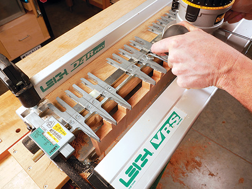
Flipping the guide finger assembly over on this jig resets it for cutting pins and tail sockets on the ends of the top and bottom panels. That was the next task, with the first pass done on a test board using a straight bit in the router this time. It took a couple of rounds of test cuts, then making small adjustments to the jig’s setup, to reach a satisfactory “push fit” of the pins into the tail board sockets. Here’s where patience and methodical procedure will pay off in the long run. Take your time.
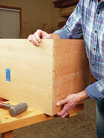
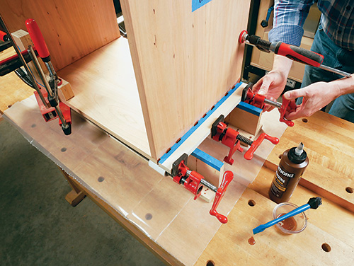
When all four panels are dovetailed, dry assemble the corner joints and check the cabinet carcass for square. Then carry out a full practice run of installing the clamps you’ll use for gluing up the cabinet so you’ll know where and how to apply pressure best. I created a plywood clamping caul for each joint that directs clamping pressure to the tails to help press them into their sockets. When everything is ready, spread glue onto the pins and into their sockets on the tail boards, and assemble the joints.
After the glue dries, flatten any protruding tails and pins with a hand plane or by sanding. Make sure the front and back edges of the carcass are also flush with one another, and plane them flat if they aren’t.
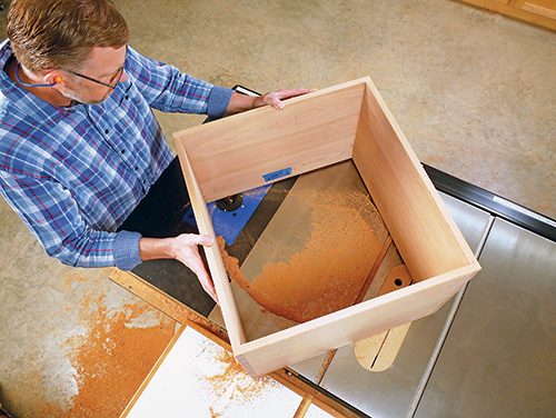
This cabinet’s 1/2″-thick plywood back panel fits into a 1/2″ x 1/2″ rabbet in the carcass back. I milled these rabbets at the router table.
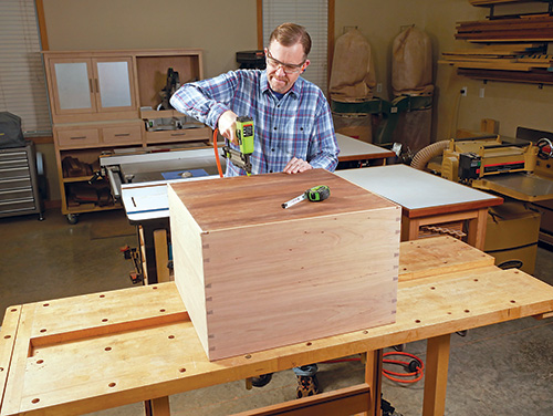
Square up their curved inside corners carefully with a chisel. Now measure and cut a walnut plywood back panel to size. Sand it smooth and install it on the cabinet carcass with 1-1⁄4″ brad nails driven into the rabbets.
Adding the Figured Slab Doors
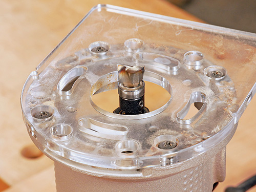
This cabinet’s 11″-wide doors are simply slabs of solid lumber. I made mine from glued-up blanks of a single piece of beautifully figured cherry. Make sure when you prepare your door blanks that the stock is as flat as possible. Trim the door blanks carefully to final length, allowing about 1/16″ of swing clearance between the door and cabinet carcass on the top and bottom.
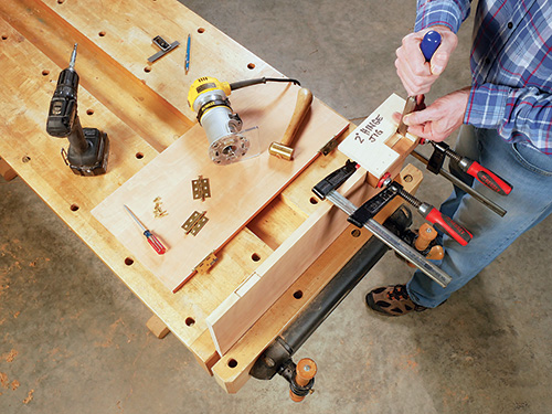
I decided to hang my doors on conventional, solid brass 2″ butt hinges. Using a simple shop-made template jig and piloted mortising bit, I routed hinge leaf mortises 2-5/8″ in from the ends of the doors on their outer edges. Mount the hinge leaves to the doors with a single screw for now. Set each door into place on the cabinet and resting on a spacer (I used strips of scrap plastic laminate) so you can mark the hinge leaf locations directly onto the front edges of the cabinet carcass. Use a knife or mechanical pencil with a fine lead to “tick” these locations carefully for an exact fit. Then rout or chisel the hinge leaf mortises on the inside faces of the cabinet. I used the same clamp-on mortising jig for this milling step.
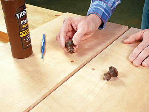
Hang the doors on the cabinet with single screws in the hinge leaves, and check the swing clearance of both doors. Then mark and trim the doors to final width, allowing for about 1/16″ of space between them. I do that by marking and trimming one door at a time, rehanging it before marking and trimming the other door. After that, I turned 1-1⁄8″ diameter walnut knobs on the lathe for my doors to give the doors one more handmade touch. I centered them on the door lengths and spread them 1-1⁄8″ apart, horizontally.
Rehang the doors so you can mark the interior of the cabinet for door catch hardware. I used brass, spring-loaded bearing catches. Install the catches, and adjust them as needed.
Accessorizing the Interior with Wire Hardware
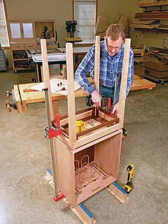
Rev-A-Shelf offers brass-colored wine bottle and stemware holders that are unobtrusive and easy to install. I mounted two wine bottle and two stemware racks to the cabinet’s inside top with screws. Then I inverted the cabinet and fastened the leg base to it with six #10 x 1-1⁄2″ wood screws. Center the leg base on the cabinet, all around.
Finishing Up
Now remove the doors and all hardware up to this point so you can apply finish to the leg base and cabinet. I wiped on several coats of Watco Natural finish to give both the walnut and cherry a pleasing amber tone. When that thoroughly dried, I top-coated the project with satin lacquer to add more durability and shine. Wait a day, then fasten the cabinet to its base again. Mount the doors and wire bottle and stemware hardware one last time to wrap things up on this involved project.
All that’s left to do is to fill your new cabinet with several bottles of your favorite vintages, wine glasses and other bottles of special spirits you may wish to store inside it, too.
Click Here to Download the Drawings and Materials List.
Hard-to-Find Hardware:
11″ Stemware Holder, Brass (2) #1001876
Double Bottle Rack, Brass (2) #1001882
Polished Brass Ball Tip Hinge, 2″ L x 1-1/2″ W (2) #26484
Brass Ball Catch, 1-29/32″ Long x 11/32″ Wide (2) #28662
