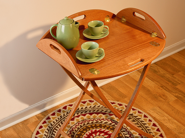
If the tray portion of this project looks familiar, you might recall that it started out as an online project completed by Rob Johnstone on a CNC Shark machine. But, I don’t have that technology, so Rob asked me to build the same tray and a folding stand to go with it using standard woodworking machines. And, as you’ll see, that is quite easily done with several templates and a router table. The matching aspects, hinge mortises and many curves of this project are much easier to manage with guided router bits than lots of exacting band sawing and drum sanding. So, gather up some nice clear mahogany, and let’s get started.
Making Wing Templates
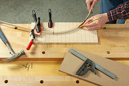
There are two approaches to creating full-size templates for the butler tray’s short and long wings: you could head to a photocopier and enlarge the gridded drawings, or draw a grid on some scrap plywood and plot several points of the curves, then join them with a strip of thin wood or hardboard bent to shape as I did. A few casing nails hammered into my half pattern registered the batten ends as I drew a half curve for both a short wing and a long wing. Then, I cut out the half patterns, faired them on my spindle sander and used them to draw full templates on some 1/2″ MDF. Now lay out the handle shape on your short wing template. Cut it out and refine its curved shape on a spindle sander or with a small-diameter drum in the drill press. (You can use the same cutout for template-routing all four handles, so save time by making just one handle cutout.)
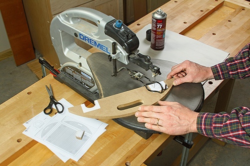
Mortising the tray’s curved brass hinges would be tough to do by hand, so I printed out a PDF that ran with Rob’s original CNC Shark article, and I used spray glue to affix two of the PDF’s hinge patterns to my short wing template. Cut these mortise shapes out with a jigsaw or scroll saw, and smooth them carefully to complete the short wing template.
Template-routing the Wings
Glue up a panel for your tray, and cut oversized blanks for the four short and long wings. Try to make all of the tray parts from one piece of stock so the grain and color are consistent. Trace the wing shapes onto their blanks, and step to the band saw to cut them slightly larger than their layout lines. Transfer the handle outline from your template to all four wings, and cut these to rough shape, too.
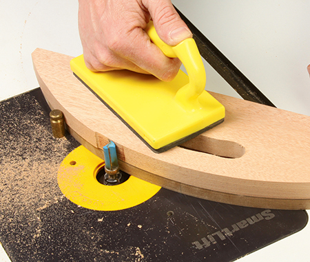
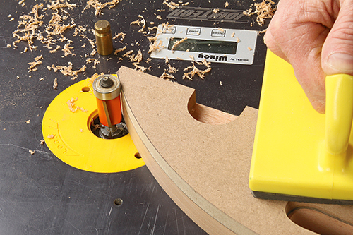
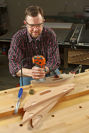
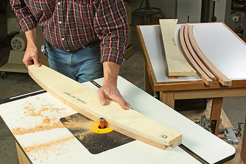
Shaving off the extra stock so your wings match their templates exactly is standard template-routing work, but with one caveat: you’re routing both end grain and long grain on these curves. Routing against end grain on the bias can lead to tearout if you feed into the curved ends, so here’s what I did instead: with the template located on top of my blank and affixed with double-sided tape, I used a large-diameter flush-trim bit — bearing at the tip — and started my cut where the long grain begins, at about the handle position, trimming off the waste and feeding left to right. Then, I flipped the workpiece over so the template was on the bottom, switched to a pattern bit — bearing on the shank — and finished trimming off the remaining overhang. With this two-bit method, you’ll always rout the end grain “with” the grain and “downhill,” so to speak, instead of against it. Use a starter pin in your router table as a fulcrum to begin each cut.
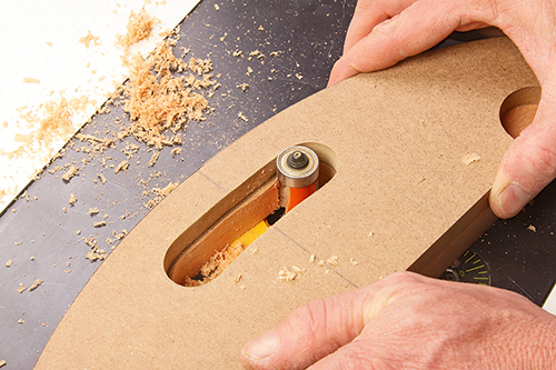
Once the outer curves of all four wings are done, double back to the flush-trim bit and rout the handles to final shape. Just use your short wing template, taped to either a short or long wing, to template-rout all four handles. Remember to feed the work counterclockwise around the bit to avoid climb-cutting.
Hinge Mortising Next
Grab your short-wing template, and trace pairs of hinge leaves onto the four wings. I positioned them 2-1⁄4″ in from the ends. The hinge barrels will require that you cut a 1/8″-deep rectangular mortise into the edges of the wings. Make these shallow mortises 1/4″ wide, and chisel them out by hand. Then clamp your short wing template into place and rout the curved hinge leaf mortises 1/8″ deep into the faces of the wings. I used a short piloted mortising bit in a trim router for this job.
Set the wings aside and cut your tray’s center panel to final size. It requires its own set of longer hinge leaf mortises that must be carefully laid out and milled in three steps. To start this process, I made a “tray side” mortise template using Rob’s PDF pattern once again (it includes full-size layouts for both wing and tray hinge mortises), spray-mounted to a piece of scrap MDF. Cut out the curved leaf shape to make this template. Now set the wings into place against the tray and transfer the exact locations of the wing hinge leaves over to the tray side. Use your new tray leaf template to mark the hinge shapes onto the tray.
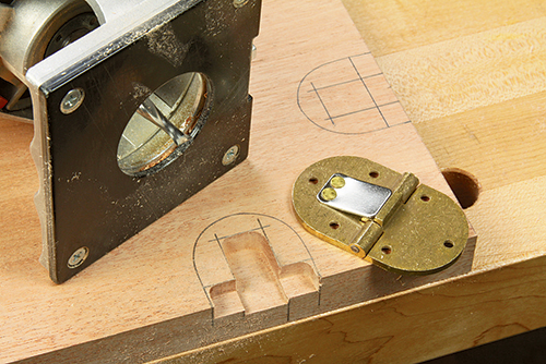
The underside of these hinges have both a recessed barrel and a steel flap that serves as a spring. I mortised for the spring first, excavating a 5/8″-wide, 3/8″-deep channel in the center of the hinge leaf area to give the spring and its adjacent brass stop full clearance. A 1/4″ carbide upcut spiral bit in my trim router was all it took, guiding the router freehand — it’s very controllable on soft mahogany if you work carefully. Then I raised the bit to 1/4″ depth to rout a 1/4″-wide slot along the wing edge for the hinge barrel; square up the inside corners of these cuts with a chisel. Last, clamp your tray-side hinge mortise template into place and zip through the eight curved leaf mortises at 1/8″ deep.
Completing the Tray
Chuck a 1/8″ roundover bit in your router, and ease the inside edges of the handle cutouts and outside curves of the wings on both their top and bottom faces. Give the tray parts a thorough sanding up through the grits to 180, and you’re ready for some “test” assembly. You’ll understand why I say “test” as soon as the hinges are screwed in place.
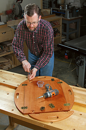
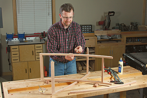
Fit the hinges into their mortises, and drill pilot holes for the tiny screws with a self-centering Vix-Bit. Now, attach the hinges, and tip the wings up gently. Do they raise to 90° and just touch at the ends? If not and the tips intersect, you’ll need to nibble a bit of material off to improve the clearance — for me, this was about 1/4″ from all eight ends of the wings. When the wings fold up properly, take the tray apart and apply your choice of finish. After the finish dries, wax the tray parts and put it all together again.
Preparing Leg Templates
Now that you are thoroughly entrenched in a templating state of mind, there are more to make for building this project’s stand. Templates make the slender legs safer to rout and ensure that the leg shapes are consistent. Any undulations or irregularities along the long curved edges of the legs are very easy to see, so uniformity and smoothness are paramount here.
I enlarged the gridded leg pattern to full size, spray-mounted it to a piece of 3/4″ MDF and cut out the shape. Primarily, this will serve as a rigid tracing pattern for your routing templates. But it also helped me make a quick mock-up with a second scrap leg to determine whether the end angles of the legs would give the stand the proper spread it needed beneath the tray.
Prepare two blanks from 6″-wide void-free plywood or MDF, about 38″ long. Trace the inside curve of your leg pattern as close as possible to the edge of one workpiece to form an “inside” leg template, and trace the outside shape of the leg pattern onto the other workpiece, close to its edge, for the corresponding “outside” leg template. Band saw these to rough shape just outside the traced lines. Now tape your MDF leg pattern securely to each template, and bring them to exact curvature at the router table with a flush trim bit. Finish your leg templates by tacking a long strip of 7/8″-thick, 11⁄2″-wide scrap wood along the bottom face of each template and flush with its back edge to complete them. (These backers will stabilize the templates during routing.)
Shaping the Legs
Choose a piece of straight-grained mahogany for your leg stock, and trace the pattern four times to form leg blanks. Head to the band saw to cut these to oversized blanks. Be prepared for possible slight springback once the parts are cut free; you may want to make them as much as 1/8″ overly wide all around just to be safe. Use the leg pattern to mark centerpoints of the legs around their faces and edges, and mark your inside and outside leg templates to reference the same centerpoints.
I chose to rout each leg to completion before moving on to the next: I routed the inside curve first, with the leg blank firmly fixed beneath the template with short strips of double-sided tape. Then I lined up my center line on the workpiece with the outside template’s centerline, taped it and flush-trimmed the leg’s other broad edge. (Keeping the center lines aligned will ensure that all the legs will be routed in the same relative positions on the two templates, in case there are any slight deviations in the template curvatures.)
Once the template-routing is done, use your leg pattern to carefully mark the angled ends of the legs. I cut these by taping the legs down to my table saw’s crosscut sled, aligning each cut to the sled’s blade kerf line. It worked great.
Forming the Cross Braces
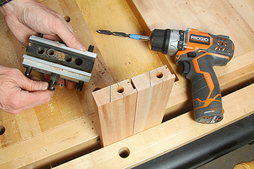
Rip and crosscut stock for pairs of long and short cross braces, but don’t bevel rip the top ends of the top cross braces yet. Before doing that, there are several preliminary steps to tackle first. You need to cut a 1/8″ x 5/8″ shallow rabbet into the bottom edges of the top cross braces to recess the metal clips that will hold the stand’s straps in place, plus a shallow kerf near the inside edge of these braces to fit the flared edge on each clip. Then lay out and drill centered holes in the ends of all four braces for the 3/8″-diameter dowels that will connect the braces and legs. Use metal dowel points inserted in these cross brace holes to find the corresponding centerpoints on the inside faces of the legs for their holes.
With this prep work behind you, tilt your table saw blade to 22° and bevel-rip the top edges of the top cross braces to match the top angles of the legs.
Assembling the Stand
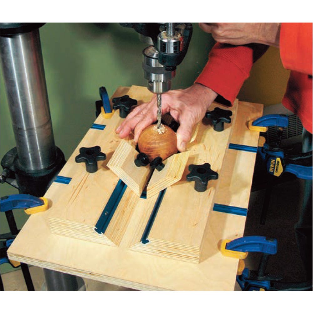
One final order of important business before putting this stand together: choose the two legs that will form the inside pair of your stand, and mark center points for the pivoting Roto hinges that will allow the stand to scissor open and closed. Drill 1/2″-diameter holes, 5/8″ deep for this hardware in the outside faces of these two legs.
If you want to soften the long edges of the legs with roundovers, do that now too, but stop the profiles where the cross braces go.
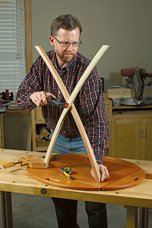
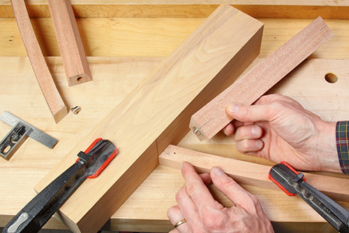
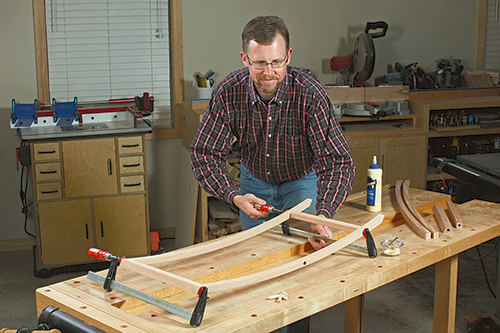
It’s finally time to bring the inside legset together with the short braces, dowels and glue to form the first leg subassembly. Once that dries and comes out of the clamps, press the Roto hinges into their holes. Add the remaining legs, longer braces and dowels to create the outer leg subassembly.
Before you glue these parts together, though, double-check that the leg angles and curves face opposite the first subassembly — an obvious thing but a complete frustration if you get it wrong and realize it is too late!
Wrapping Up the Final Details
The end of this elegant little project is close, but there are still a few more steps. Drill 1/8″-deep, 1/2″-diameter holes in the angled edges of the top cross braces in order to partially recess four rubber bumpers. Screw them in place.
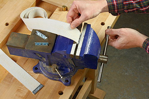
Now invert the stand on your bench and hold it open so the bumpered cross braces rest flat on the bench (the spread should be about 18″). Cut two strips of chair webbing 1″ longer than the inside span between the legs. Then, fit the webbing fully inside the metal clips, and close the clips by squeezing them in a vise. Make sure the flared edges of the clips face the same direction on each of the straps before pinching the second clip closed. (Again, it’s common sense here, but Murphy’s Law is in full effect for me when a project is nearly done!)

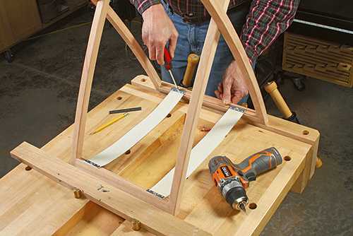
Fit the clip flares into their kerfs in the top angled cross braces, and secure the clips with short screws to complete the stand. I then removed the straps but used a length of string tied to the clip screws to keep the stand upright and open. It was convenient as I applied a spray lacquer finish.
Enjoy your new project and a woodworker’s brush with Old World aristocracy.
Hard to Find Hardware
Brass Butler Tray Table Hinges #81258
Roto Hinges #36251
Non-Skid Rubber Bumpers #45929
Chair Webbing #40998
Click Here to Download the Drawings and Materials List for This Project.