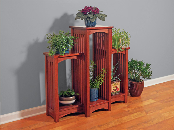
Slatted Arts & Crafts-style plant stands are timeless, but many look pretty ho-hum. I wanted to breathe some new life into this classic, so art director Jeff Jacobson and I decided to join two shorter plant stands to a taller center unit and break the front plane of all three. It triples the number of plants you can display while adding some pleasing visual details. Mine is made of quartersawn mahogany, but white oak, walnut or cherry would be other attractive choices. Regardless, you’ll need both 8/4 and 4/4 stock to build it.
Initial Surfacing and Getting Organized
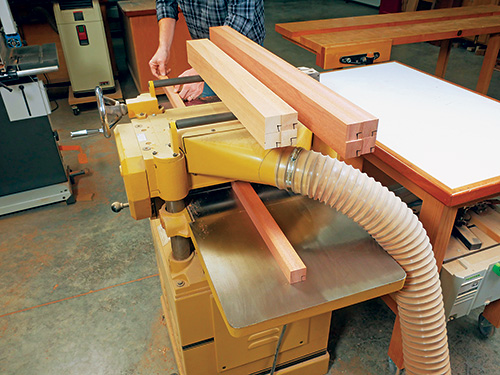
On many projects, it makes sense to prepare your lumber as you need it while you build. But for this plant stand, you’ll gain some efficiency during the repetitive joinery stages if you make up most of the part blanks now, at the beginning of the building process. So that’s what we’ll do first.
Start by surfacing and rip-cutting enough 8/4 stock down to 1-3/8″ x 1-3/8″ to make four 36″-long legs for the taller center unit and four 25-3/4″-long shorter legs for the two outer units (two legs per outer unit), plus at least one “test” leg to use for dialing in your mortise sizes.
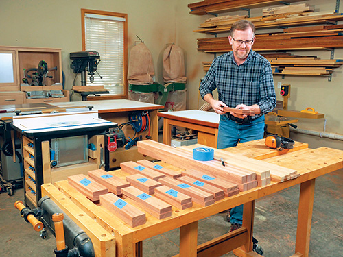
You’ll need eight rails for the center unit and a total of 12 rails for the two outer units. Let’s make blanks for all of the 2-1/4″-wide rails first, following the Material List. Rip several long strips of stock to 2-1/4″ wide, and crosscut them to the following lengths for the center unit: two at 10-1/4″ for the top side rails and two at 11″ for the top front and back rails. Crosscut two top side rails to 7-1/4″ for the outer units, then cut two more to 12-1⁄8″ for the top back rails. You’ll need two top front rails for the outer units as well; cut these 1/4″ overly long. And while you’re at it, crosscut two blanks for the center unit cross supports, making them about 1/4″ longer than specified.
Continuing with rough stock preparation for the rails, rip several long strips to 3″ wide. Follow the Material List lengths to crosscut blanks for the center unit’s two bottom side rails (10-1/4″) plus a front and back bottom rail (11″). The outer units will need two bottom side rails (7-1/4″) and two bottom back rails (12-1⁄8″) cut to length. Crosscut two bottom front rails for the outer units as well, but make these 1/4″ overly long. Label and group these rail blanks carefully to avoid confusion.
Blanks for the plant stand’s side slats can happen next. Prepare enough 1/2″-thick stock to rip a dozen slats for the center unit and two spares at 1″ wide. Crosscut these 1/4″ longer than needed at 31″. Rip 10 slats for the outer units (eight required plus two spares), and make them overly long at 20-3/4″. We’ll trim all the slats to final length later.
Laying Out Leg Mortises
Arrange the legs into the orientation you’ll want them to be in when the plant stand is assembled, and mark their ends to make this clear. Then follow the Drawings to mark all the 1-1/2″-long mortises on one long leg and one short leg. All the mortises are centered on the leg thicknesses. Transfer these locations with a square onto the other legs — there’s no need to measure if you use the original marked legs as your guides. Notice in the Exploded View drawing that the back two legs of the center unit have two extra mortises that receive the top and bottom back rails of the outer units.
Mortises for the plant stand’s 20 slats are all 1/4″ wide x 1/2″ long and spaced 1-1/2″ apart from center to center. Mark their locations on the inside edges of the top and bottom side rails of both the center and outer units, using the Drawings as layout guides.
Milling Leg/Rail Joinery with an FMT Pro Jig
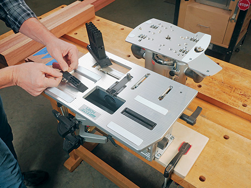
But you can certainly use a router and an edge guide, a hollow-chisel mortiser or a drill press and Forstner bit to cut these mortises instead. These options will work fine, too. Cut all the rail and leg mortises 9/16″ deep, which leaves a bit of extra depth for excess glue to pool at the bottom.
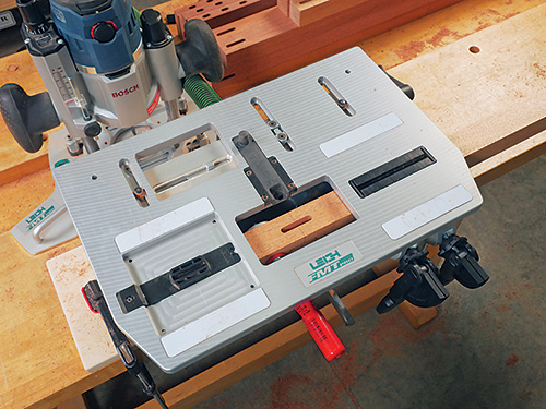
When the dust clears from mortising, go ahead and machine tenons to fit them. Here again, the Leigh FMT Pro makes this process easy. It enables tenon workpieces to be clamped vertically against the jig’s body for routing. The same plastic template for the mortise guides the tenon-cutting process, too. This time, tracing around the perimeter of the template with the subbase pin directs the router for milling the tenon with a spiral bit.
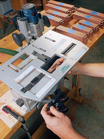
But you can use whatever tenon-cutting method you prefer. All of the tenons on the rails and slats are 1/2″ long. Be sure to keep in mind that one end of the top and bottom front rails of the outer units have no tenons where they butt against the cross supports and bottom side rails of the center unit.
Creating Side Assemblies for the Center Unit
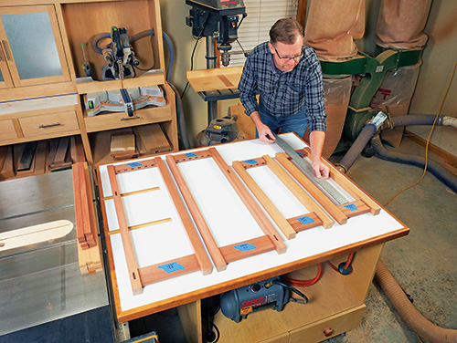
Dry-fit the top and bottom side rails to the legs to create frameworks for two side assemblies of the plant stand’s center unit and one side assembly for each shorter outer unit. Make sure the top edges of the top side rails are flush with the top ends of the legs. Now measure between the rails in order to double-check the slat lengths. The distance between the inside edges of the rails, plus 1″, equals the overall slat length.
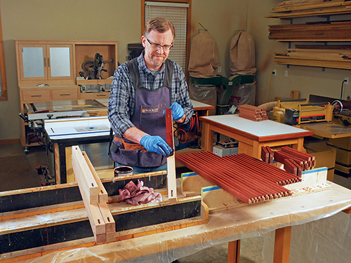
Trim all the slats to final length. Then raise tenons on their ends, using whatever tenon-cutting process you prefer, and install them in the side assembly frameworks to check their fit. If the parts go together well, sand the legs, side rails and slats up through the grits to 180 and ease their sharp edges.
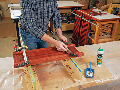
This plant stand will have a lot of nooks and crannies to contend with if you assemble it all before staining and finishing. Pre-finishing the parts in stages before putting them together simplifies things here and minimizes potential frustration. It also makes glue easy to wipe away. I stained the legs, slats and side rails with an oil-based red mahogany stain, sealed it in with a coat of dewaxed shellac and then topcoated with aerosol satin lacquer. Be sure to keep the finish off of the tenons and out of the mortises. When that cures, glue and clamp all four side assemblies together.
Detailing the Front and Back Rails
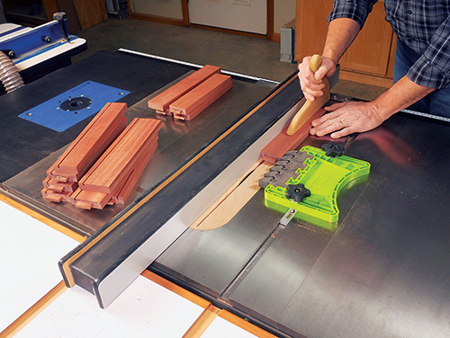
We’ll make top panels and shelves of this plant stand from solid wood, so cross-grain wood movement of those pieces needs to be taken into account. Rockler’s steel Table Top Fasteners are a good solution here: one end of these offset fasteners fits into a saw kerf on a rail or apron, and the other end screws to the bottom face of a panel. This way, the fastener allows the panel to expand or contract while still holding it securely. We can prepare for this hardware now by cutting a kerf along the inside face of the 12 front and back rails at the table saw with a standard blade. Position the kerf 7/16″ in from one edge of each rail. Make the kerfs 5/16″ deep; they can run the full length of the rails.
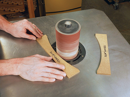
Once those are done, the front and back rails of the center and outer units are ready to receive a broad arch along their bottom edge. The large radii of these curves are 10-5/8″ for the center unit and 13-5/16″ for the outer units, and the apex of these curves extends 1″ up from the bottom edges of the rails. To cut them uniformly and efficiently, I first created two rail templates from scraps of 1/4″-thick MDF — one for the center unit and one for the outer units. Cut out the templates and sand their bottom curves smooth and fair.
Use the templates to trace an arch onto each of your rail workpieces. Notice in the Drawings that the curves are centered on the lengths of the center unit’s rails. However, on the outer units these curves are centered on just the top and bottom back rails. On the top and bottom front rails, the arches are actually offset. Locate them so the curves begin 1/2″ in from the tenon shoulders on the outer ends of these particular rails.
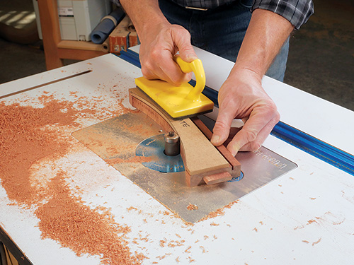
Rough-cut the curves at your band saw or with a jigsaw, cutting about 1/16″ outside your layout lines. Then adhere the hardboard templates to each rail with strips of double-sided tape, and template-rout them to final shape on the router table with a piloted flush-trim bit. Touch up these arches at your drum sander to remove any router bit marks before you final-sand, stain and finish all 12 side rails.
Putting the Pieces Together
At this point, assembling the center unit is a snap! Spread glue on the rail tenons and into the mortises of the side assemblies. Bring the whole framework together with clamps.
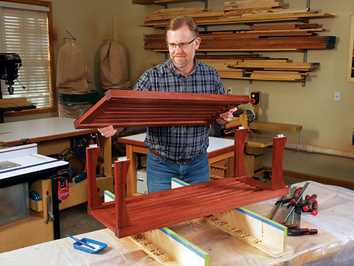
While those joints set, glue up panels for the three tops and shelves. In order to contend with wood movement, be sure to orient the long grain of these six panels so it will run left and right on the finished project, not front to back. This way, the panels can expand and contract outward without being constrained by the legs. When the tops and shelves come out of the clamps, finish-sand them and set them aside for now.
Round up the two cross supports you made earlier for the center unit and cut them to length, making sure they fit snugly between the legs. I trimmed the ends of their outer faces to 45-degree bevels; size these bevels to 5/16″ x 5/16″ so they’ll transition the front face of the cross supports nicely into the leg faces. Sand the cross supports up to 180-grit, and apply stain and finish to complete them.
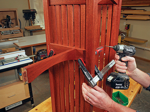
Position and clamp the cross supports to the side slats of the center unit so the top edges of the cross supports are 25-3/4″ up from the bottoms of the legs. Then dry-fit the top and bottom back rails of the outer units as well as their slatted side assemblies to the center unit, clamping these components into place. Now measure the distance between the inside faces of the front legs and the cross supports to verify the final length of the top front rails. Trim the un-tenoned ends of these rails to that length. Repeat this process for measuring and cutting the bottom front rails to length.
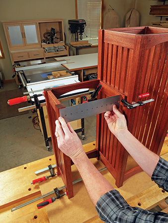
Dry-fit the top and bottom front rails of the outer units into place and mark their locations on the cross supports and bottom side rails of the center unit. Then dismantle the outer units so you can attach the cross supports to the top front rails with pairs of 2″ countersunk wood screws driven through the cross supports. Now attach the cross supports to the center unit by driving two #6 x 1″ flathead wood screws through each outermost slat and into the cross supports.
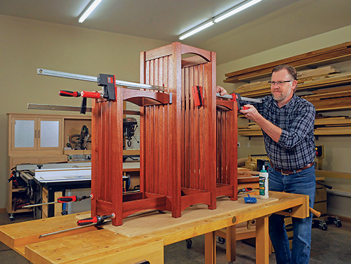
With those installed, dry-fit all the rails and side assemblies of the outer units to the center unit one last time to check all the remaining unglued joints. If everything is shipshape, bring the three plant stand frameworks together with glue and clamps. Attach the bottom side rails of the center unit to the bottom front rails of the outer units with pairs of 2″ countersunk wood screws driven from inside the center unit.
Installing Tops and Shelves
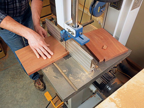
We’re in the homestretch now! Crosscut the tops and shelves to final length. Notch the back inside corners of the top panels and shelves of the outer units so they’ll tuck around the back legs of the center unit. Then soften the edges of all these panels and apply stain and finish. I switched to satin polyurethane here; it offers better protection than lacquer against those inevitable spills that are bound to happen when watering plants.
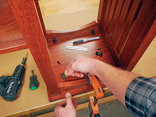
To install the tops and shelves, insert two tabletop fasteners per rail into each of the saw kerfs and locate them about 1-1/2″ in from the rail ends. If you’re building this project during the wintertime when these panels are fully contracted across the grain, back the tabletop fasteners about 1/16″ out of their saw kerfs to give the panels room to expand in the summer. Fasten them to the top panels with the included screws.
