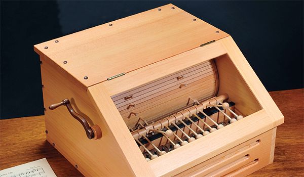
Before the turn of the 20th century, mechanical musical devices such as orchestrions and hurdy-gurdys (the kind used by monkey-wielding organ grinders) were all the rage, providing people with popular tunes in the days before gramophones and radio. Even today, in the age of MP3 players and streaming audio, you can still buy small wind-up music boxes that plink out sweet, tinkly tunes that delight the ears.
I thought it would be an interesting challenge to create my own version of a music box, built from mostly wooden parts. The one I came up with is based on an antique hand-cranked barrel organ. Here’s how it works: A drum, made of narrow slats attached to a pair of end discs, rotates as it’s driven by a hand-cranked pulley. As the drum rotates, small pins that pivoting blocks, each of which is fitted with a small round mallet at the end of a rod. As the pin rotates past, it releases the pivot block and the mallet falls and strikes a metal xylophone tone bar, thus producing a musical note. There are a total of 15 mallets and tone bars, and the pattern of pins on the drum determines which notes are struck — and, hence, the tune the music box plays. I arranged the pins of my music box to play “Heart and Soul,” but it could be set up to play just about any short song. The entire mechanism fits into a case with an angled front covered by a glass-paneled door, so you can see the mechanism operate as the song plays.
It’s not an easy project to build, but, when you are done, it sounds great and is fun to operate.
Cutting the Slats
The pin-bearing drum is the heart of the music box, and its surface is made up of 64 individual slats — enough to play a song that’s eight measures long, with each individual measure divided into one whole note, two half notes, four quarter notes, eight eighth notes, or any combination thereof. Each pin set into the drum activates one note at a time, and their arrangement determines the tune the music box will play. To create a “map” of the location of the pins in the slats (somewhat akin to “composing” your song), visit More on the Web to see my instructions and chart.
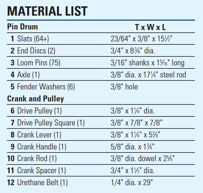
When choosing wood for the slats, to prevent problems from expansion and contraction, it’s best to use only well-dried, straight-grained, quartersawn stock. I chose vertical grain Douglas fir and oriented the slats with the radial grain facing up. After thickness-planing the stock to 3/8″ thick, crosscut the blanks to 15-1/2″ long. Set the table saw’s rip fence for a 2-3/64″ cut (just 1/64″ under 3/8″) and rip 64 slats, plus a few extras. Mark one face of each slat to keep them properly oriented.
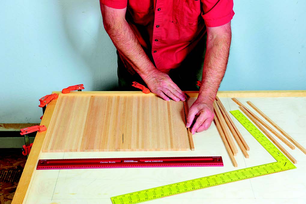
Next, make an alignment board from a flat piece of plywood or MDF that’s at least 2-1/2 feet square. Clamp a pair of straight strips flush with two adjacent edges, using a framing square or triangle to assure that the strips are exactly square to one another. Now lay the slats atop the board face-up and flush to the alignment strips so that they form a continuous sheet, like for a tambour door. Reject any slats that are warped or wonky. Number the end of the slats sequentially, moving from right to left. Underline the numbers 1, 6, 8, 9, 11 and 19, to avoid confusing the slat’s top and bottom surfaces.
Drilling the Holes
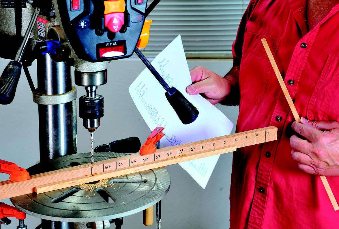
The next step is to drill holes in the slats for the loom pins (available from craftparts.com, item TP1030) that will trip the pivots when the drum turns. After creating a song layout sheet (see online instructions), remove only the slats that will receive pins, leaving the slats that don’t need drilling on the alignment board. To make drilling quick and accurate, create a 3/4″ x 1″ x 30″ positioning fence for the drill press, marked with a series of perpendicular lines: The first line at the center of the fence marks the centerline of the 3/16″-diameter drill bit. Draw the next line 3/4″ to the right of the first line and label it “G3,” for the highest note on the xylophone. Space each subsequent line 1 inch to the right of the previous line, and label it with the next lowest note: F2, E2, D2, etc., all the way down to G1, the lowest note. After aligning the fence center mark to the bit and setting the fence so that slats will be drilled on center (widthwise), clamp it to the drill press table. Now, with a slat face-up and its numbered end on the left, line up the slat’s right end with the desired note you wish to drill a hole for and bore the hole 5/16″ deep. Align the slat to other note marks, as indicated by your song layout sheet, to drill subsequent holes. Do this with the remaining slats until all the holes are drilled.
Creating the Slat Assembly
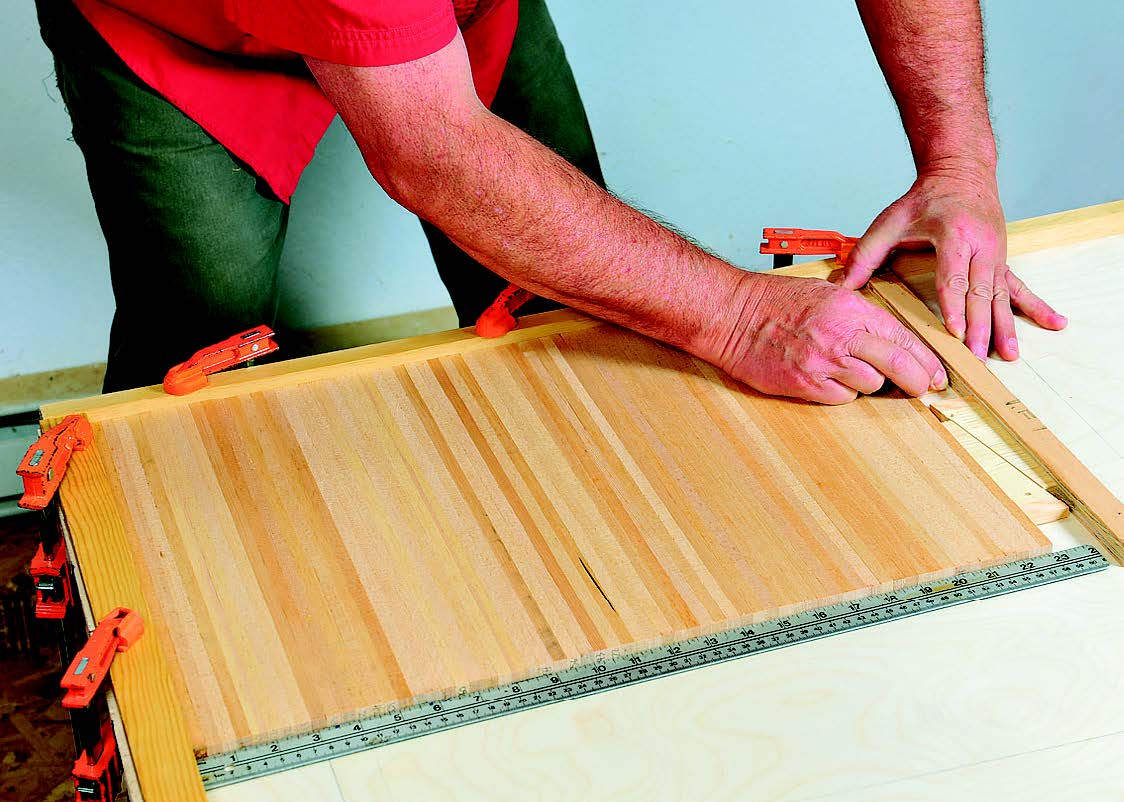
To make it easier to attach the slats to the end discs that form the drum, a piece of canvas is glued to the back of the assembled slats, in the same fashion used to create a tambour door. First, return the slats to the alignment board, each face up with the numbers running right to left. After doublechecking to make sure the numbers are in proper order, flip the entire slat assembly over so that it’s facedown on the board; the numbers should now be upside down, and run from left to right. Press the slats tightly together and flush to the alignment strips, then nail or screw a straight scrap of wood parallel to the slats, about two inches from the end of the last slat. Cut a pair of wedges from scrap 3/8″-thick stock, each with a 10˚ complementary angle. Set the wedges in the space between the slats and end strip, then press the wedges firmly against each other. This effectively clamps the slats tightly together, eliminating any spaces between them.
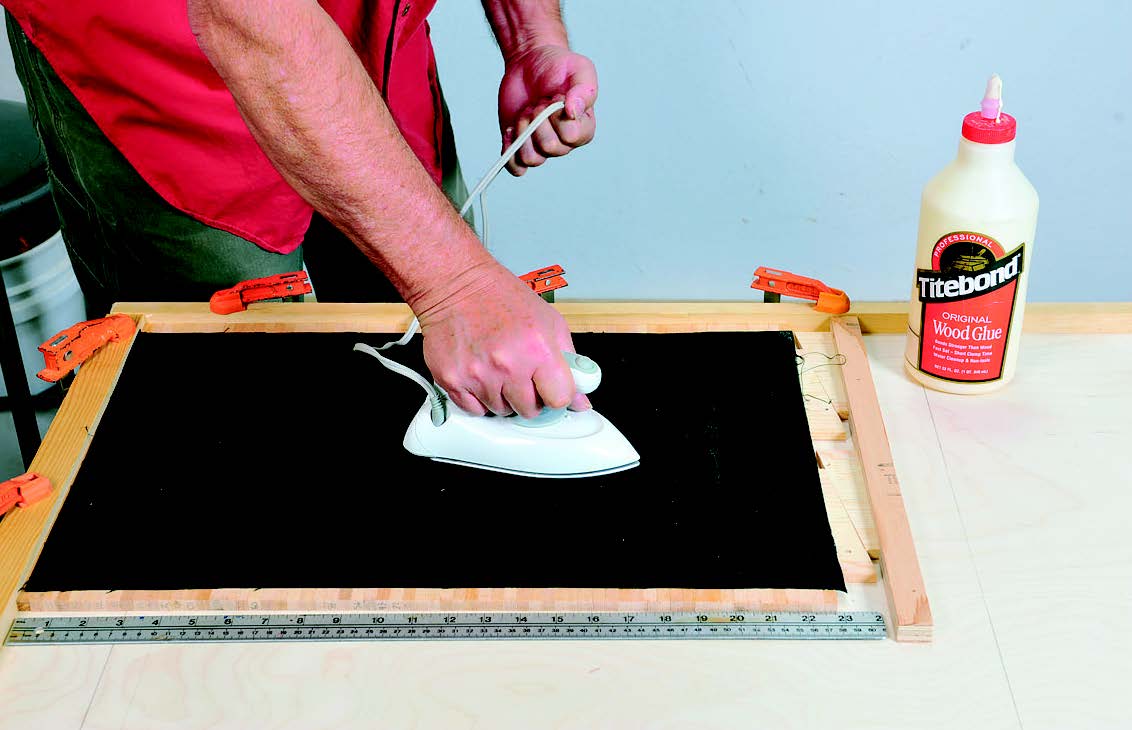
Cut a piece of 12-ounce duck canvas that’s 14-1/2″ wide and a little longer than the slat assembly. Apply yellow glue liberally to the surface of the canvas, spreading it evenly with a squeegee. Turn the canvas over, center it on the slats and press it down, working from the center to the edges to remove wrinkles and air bubbles. Next, use an old household iron set to the “wool” setting to quick cure the glue. After waiting about 10 to 15 minutes for the canvas to cool, remove the assembly and flex each joint between adjacent slats. Sand the slat faces to final smoothness.
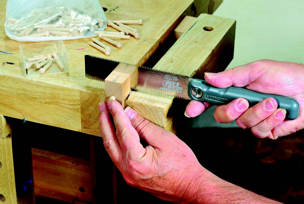
Before inserting the loom pins, trim them to their correct 1-5/16″ length using a simple sawing jig. Cut the jig’s kerf square and perpendicular to its hole and position it 1-1/16″ from the left-hand end of the block.
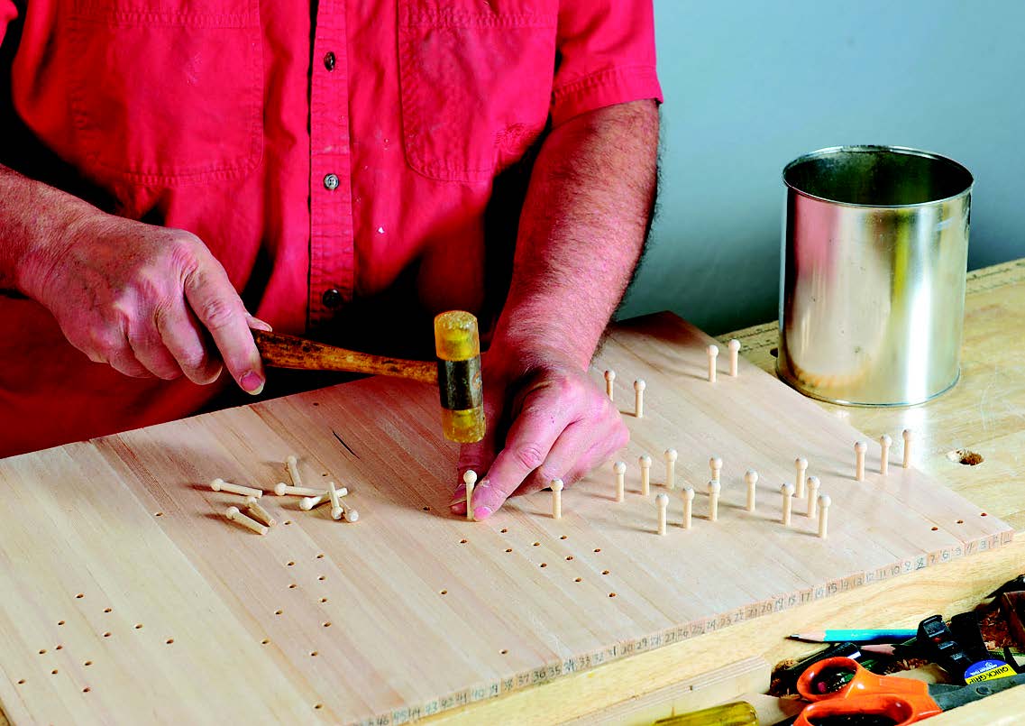
The pin to be trimmed is inserted up to its head in the hole, then cut with the saw (the next pin pushes the waste piece out through the hole on the other side of the block). Now, with the slat assembly on the workbench, gently tap the loom pins into their holes.
Making the Drum Discs
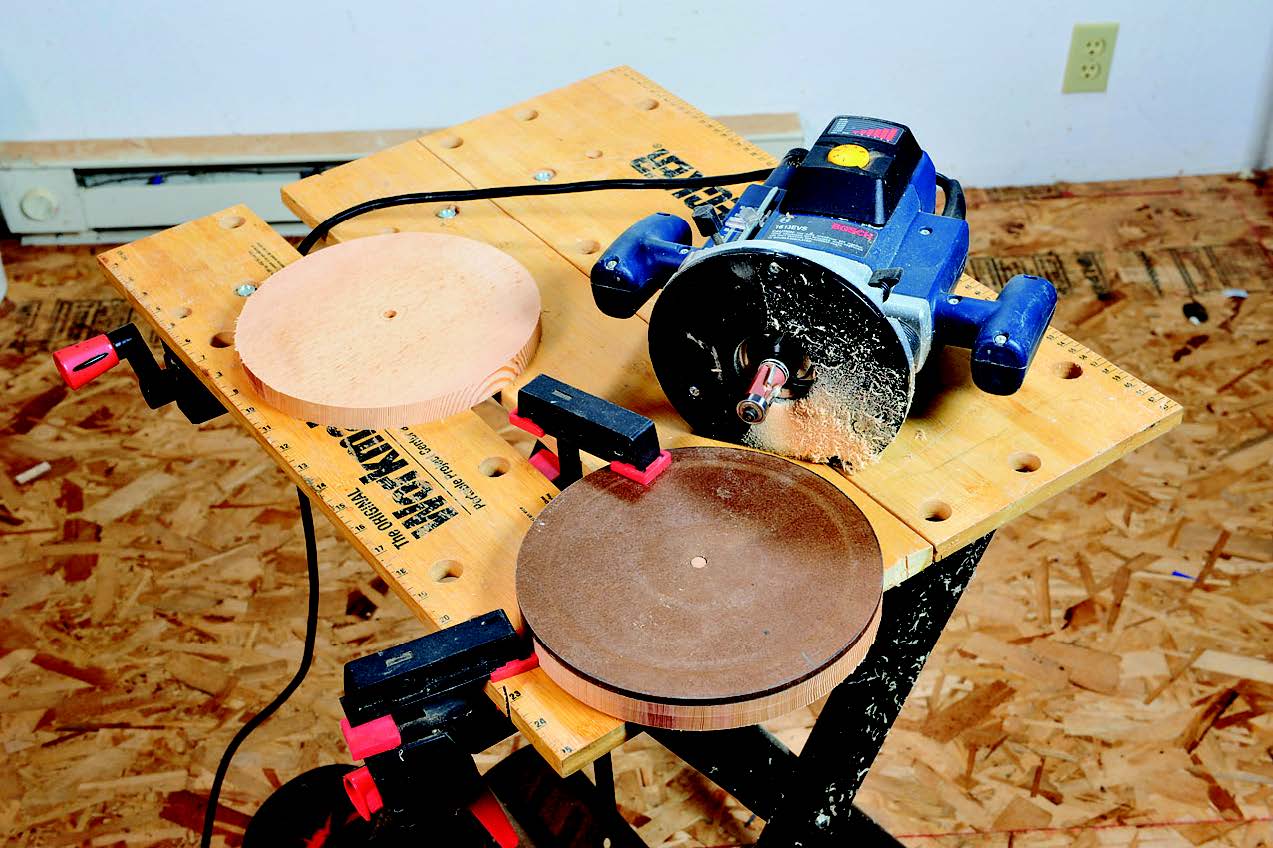
A pair of 3/4″ wood discs make up the ends of the drum. To assure that both discs are perfectly round and exactly the same size, turn a template on the wood lathe: First, drill a 3/8″-diameter hole in the center of a blank cut from 1/4″ hardboard. Mount this on the lathe and turn it to exactly 8-3/8″ in diameter. Cut two disc blanks and drill a 3/8″ hole in the center of each. Rough-cut these round, making each just slightly larger than the final diameter will be. Use a piece of 3/8″-diameter dowel to align the template to the blank, then use double-stick tape to temporarily fix the template atop the blank.
Now, with a piloted flush-trim bit in the router, carefully trim the disc to final size. Repeat with the second disc. Next, mount a rabbeting bit in the router with a pilot bearing set to cut a shoulder that’s 1/2″ wide. Adjust the bit’s cutting depth to 3/8″ and run the bit around one side of both discs. Mount one of the discs on the lathe and use a small gouge to form a shallow U-shaped groove around the rim, for the 1/4″ round urethane drive belt that will turn the drum (available from polybelt.com). Now is a good time to also turn the 1.”-diameter drive pulley, which also receives a U-shaped groove. Also turn the crank handle and spacer, and cut out the crank lever and drive pulley square. Drill a small countersunk hole in a side of the square, for the locking screw, and glue the square to the side of the drive pulley, aligning their holes with a scrap dowel.
Assembling the Drum
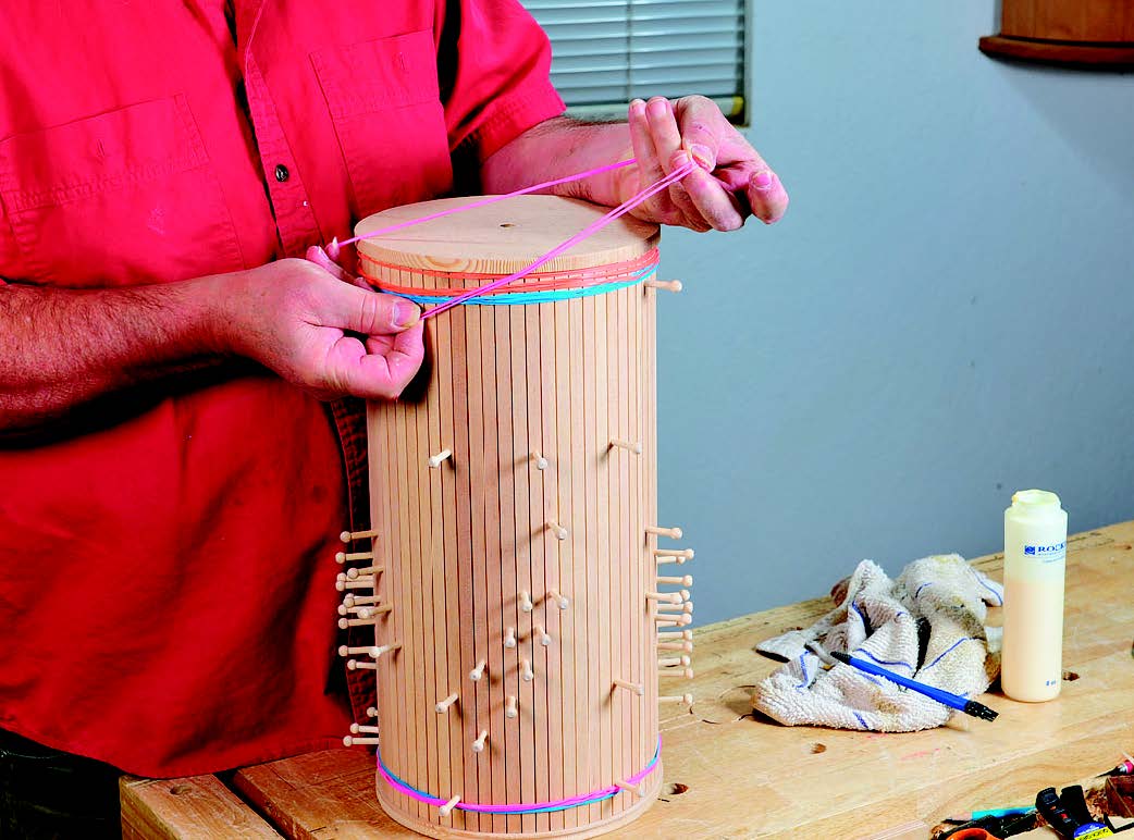
To join the drum parts together, set the pulley-groove disc rabbet side up on the bench and insert the 3/8″ steel rod axle into its center hole. Now wrap the slat assembly around the disc, with the numbered ends pointing down. Set the slats into the rabbet, then put a couple of large rubber bands around the bottom of the slats, to hold them in place. At the top of the assembly, apply glue to the ends and inside edges of the slats as well as the rabbet in the other drum disc. Fit the disc onto the slats, making sure their ends are flush with the disc shoulder, then pull on enough large rubber bands to clamp the slats tightly against the disc. Once the glue is dry, flip the drum over and repeat the gluing process with the pulley disc. To fill the small gap between the first and last slats, cut one of the extra slats to the necessary width, then glue it in place.
Building the Mallet Pivots
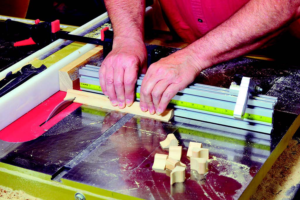
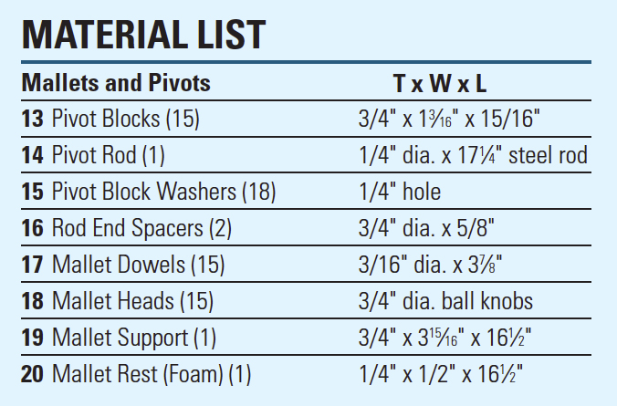
The music box’s notes are played by 15 ball-headed mallets, one for each tone bar. Each mallet attaches to a pivot block, shaped as shown in the Drawing. The easiest way to make the pivot blocks is to create a “loaf” (a long strip that’s been shaped to the profile of the blocks), then cut the individual blocks off one at a time. Start by ripping a piece of stock to 3/4″ x 1-3/16″ x 20″. Take a 1/2″-radius cove router bit, remove its pilot bearing, and mount the bit in the router table. Set its height and the position of the table fence to cut a cove shaped as shown in the Drawing, above. It’s best to rout the cove in two passes: The first pass removes most of the waste; the second trims the cut to its final size. Use a 1/4″-radius piloted roundover bit to shape the profile on both top edges of the loaf strip, then sand the strip smooth. On the table saw, use a miter gauge to cut the 15 individual 15/16″-long pivot blocks from the loaf.
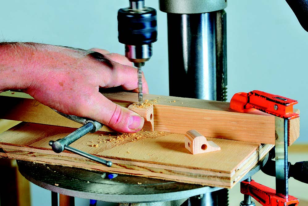
Each individual block now receives two holes: a pivot hole for the 1/4″-diameter steel rod that supports all the blocks; the other for the 3/16″ mallet dowel. To drill the pivot hole (positioned as shown in the Drawing above), chuck a 17/64″-diameter bit and drill lengthwise through each block. Next, chuck a 3/16″-diameter bit and bore the holes for the mallet dowels. After gluing the ball knobs (craftparts.com, item KBB075) onto the ends of the mallet dowels, press them into the pivot blocks (don’t glue them yet). Slip the blocks onto the 1/4″ steel pivot rod, fitting a single 1/16″-thick washer between each one. Make the two end spacers by center drilling a pair of 5/8″-long, 3/4″-diameter dowels, then slip them onto the ends of the rod, adding washers at the outside ends.
Creating the Xylophone Rack
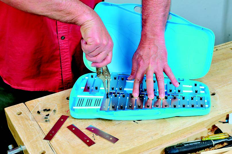
The music box uses metal tone bars taken from an inexpensive xylophone (the Lyons 25-note xylophone, available from Amazon.com). First, use a pair of needlenose pliers to remove the pins and grommets that secure the 15 chromatic tone bars (not the sharps and flats) to the plastic case. Carefully peel up the two foam strips that the bars rested on and set them aside where their adhesive strips won’t get fouled with sawdust.
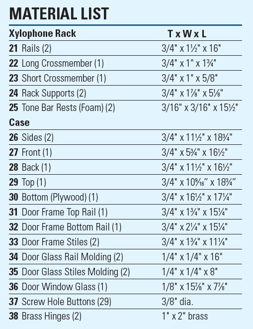
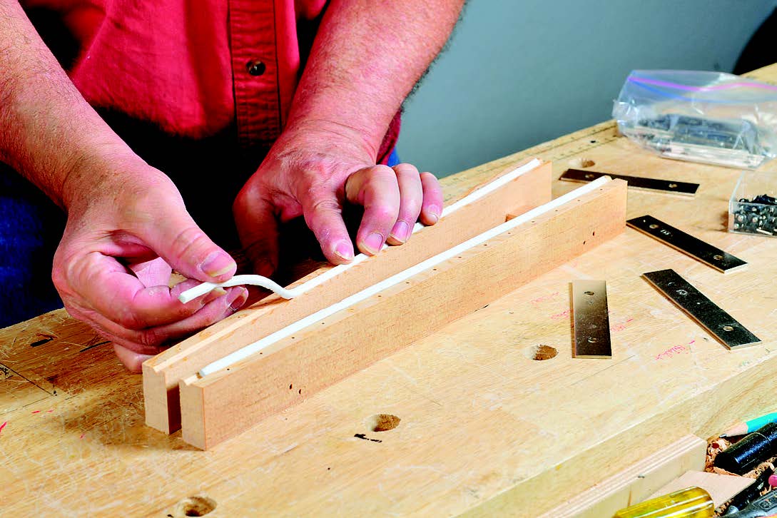
To make the new rack to support the tone bars, cut the two rails and two crossmembers, sized as per the Material List. Chuck a V-groove bit in the router table and plow a 3/16″-wide groove, spaced 3/16″ from the rail’s inside edge, along the length of each rail. Next, drill 15 holes 1/16″ in diameter for the tone bar pins in each rail, spaced one inch apart relative to the centerline of the rack. Glue the crossmembers between the rails, making sure the spacing between the holes for the widest tone bar is 2-3/4″, and 1-7/16″ for the narrowest. Stick the foam strips you removed earlier into the rail grooves, then mount the tone bars by gently tapping the pins/grommets into their holes.
Making the Case
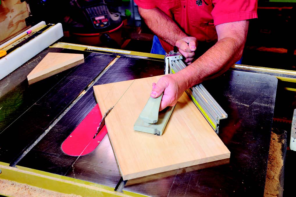
After cutting all the case components to size as per the Material List, trim a 35˚ triangular piece from the top forward edge of each side (see the Drawing) on the table saw, using an accurate miter gauge to guide the cut. At the drill press, bore the 3/8″ and 1/4″ holes in the case sides, positioning them as shown in the Drawing for the drum axle, crank rod and pivot rod. Only the crank hole goes all the way through; the others are bored 7/16″ deep. After sanding the sides smooth, glue on the crank spacer, using a tape-covered dowel scrap to align it with the crank hole. To make assembly simpler (as well as allow disassembly, in case future repairs are needed), the bottom, sides and top of the case are butted together and joined with 2-1/2″-long #8 construction screws. Space the holes in the sides 3/8″ from the edges; space the top holes 3/4″ from the edges. Drill all holes with a #8 countersinking drill, boring each hole deep enough to form a 3/16″-deep, 3/8″ counterbore, to accommodate the wood buttons that hide the screws.
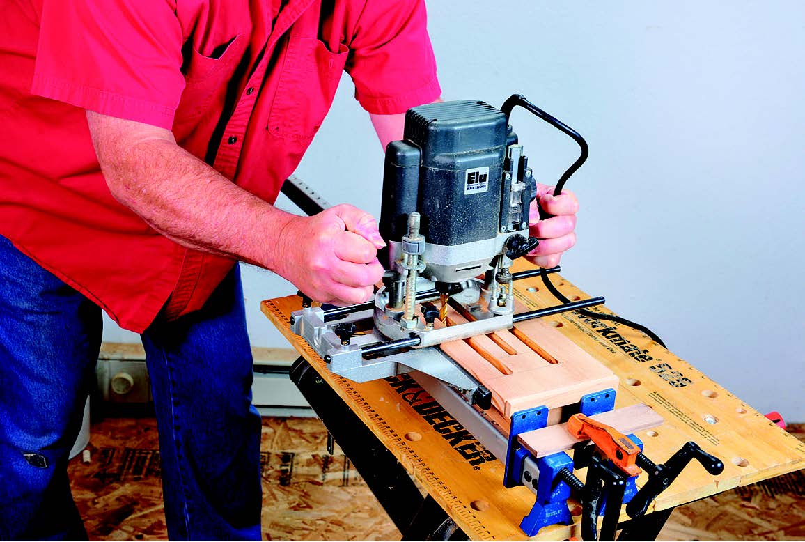
Next, rout three slots on the front of the case to allow the sound of the music box to be heard without lifting the top. Make these slots with a 1/2″-diameter spiral fluted bit in a plunge router fitted with an edge guide. Clamp the ends of the case front with a pair of bar clamps, placing a scrap piece between the piece and the clamps, then secure the bar clamps to the work table. Mark out the slots (see the Drawing) on the front, then set the router’s fence, start the router, and plunge the bit to cut each slot all the way through the workpiece.
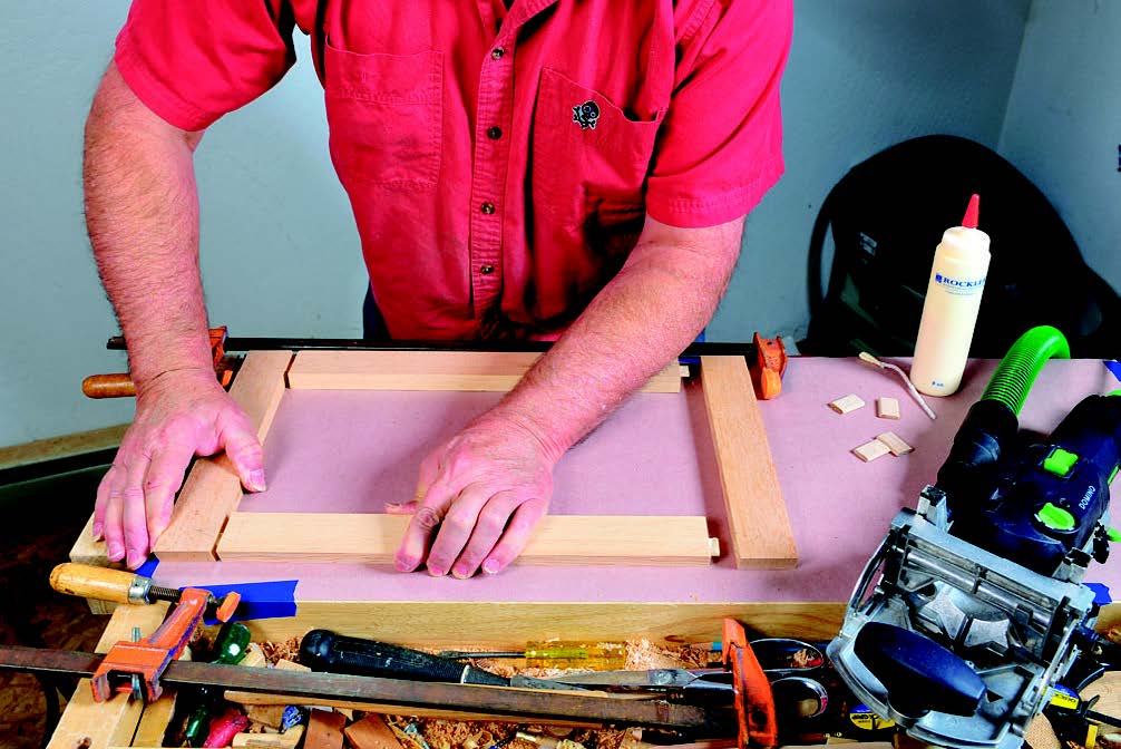
To make the frame for the angled glass door at the front of the case, cut the stiles and rails to length, noting that the extra length of the stiles and width of the rails allows for beveling of the frame’s edges later (see the Drawing). You can join the frame members with dowels or with loose tenons, such as those cut by Festool’s Domino tool. Once the frame is glued up, rout a 7/16″-deep, 3/8″-wide rabbet (for the window glass) around the inside of the back side of the frame, using a piloted rabbeting bit. Square up the corners with a chisel. Next, on the table saw, cut a 17.5˚ bevel on the back edge of the frame, as well as on the front edge of the case top. Mortise the back edge of the frame, as well as the forward edge of the case top, to hold a pair of 2″ x 1″ hinges, each spaced 2-3/8″ in from the frame edges. Chop out both 1/16″-deep mortises by hand with a chisel, then drill pilot holes for the hinge screws.
Make the molding strips that hold the glass in the frame by first routing a length of stock with a 1/4″-radius piloted router bit, then cutting off a 1/4″ by 1/4″ strip on the table saw. Now set the table saw blade to a 35˚ angle and bevel the front edge of the glass frame, as well as the top edge of the case front. Use a small router and piloted 45˚ bit to put a small chamfer around all the edges of the frame and top (but leave the hinged edges unrouted). Also chamfer the top and the ends of both case sides; these create reveals where the sides join the front and back.
Assembling the Music Box
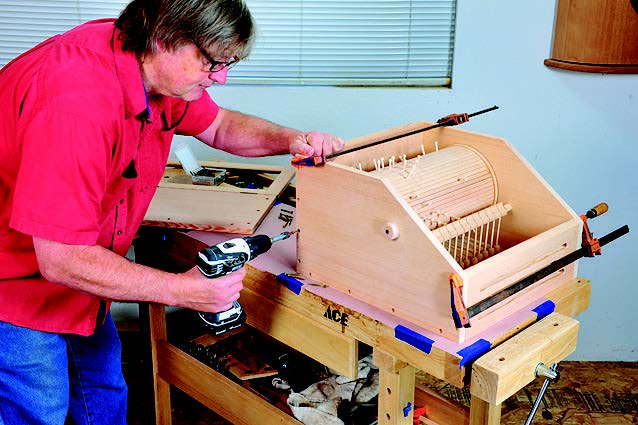
Before final glue-up, preassemble the case, setting the drum and mallet pivot block assemblies into place and temporarily clamping all the case parts together. Use a 3/32″ bit to bore pilot holes through each case side, then screw the parts together. To make sure that the music box will play correctly, set the mallet support (with the foam mallet rest strip, piece 20, you’ve made from weatherstripping adhered to its top edge) and xylophone rack and supports into place and check the fit and alignment. The mallet heads should be centered on the tone bars and come to rest about 1/16″-3/32″ above them. You can adjust this by trimming (or shimming) the mallet support and/or the xylophone rack supports. Once the notes sound crisp, screw the rack to the supports, and the supports to the mallet rest.
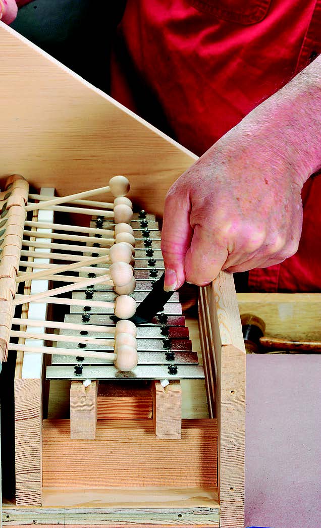
It’s best to pre-finish all music box parts before final assembly. I chose to spray lacquer them, but you can use any finish you choose (just mask off any edges that will be glued up). Begin assembly by gluing the front and back to the plywood bottom, making sure they’re flush and square. After screwing the crank handle to its lever with a #6 x 1″ screw and gluing the lever to the crank rod, slide the assembly into the case side. Fit the drive pulley and secure it to the rod with a #4 x 3/4″ screw, driven through the pulley square. After screwing on one case side, set the axle at the pulley end of the drum and the mallet pivot rod into their respective holes. Slip the belt over the drum, then fit the other case side and screw it into place. Set the glass into its frame and secure it with the molding strips, each attached with a few small brads carefully driven. Screw the case top on, then mount the hinges that attach the glass frame. Set the xylophone rack/mallet rest assembly into the case, securing it with a couple of screws driven through the rack supports. Tap wood buttons into all the screw holes, then slip the urethane belt onto the drive and drum pulleys.
Now you’re ready to turn the crank slowly (clockwise only!), and enjoy the beautiful tune your music box plays.
Click Here to download a PDF of the related drawings.
