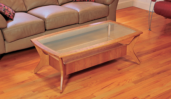
“Well, I guess you won’t be putting your feet up on that table again.” That’s what my wife said (with a somewhat sympathetic tone of voice) when I clumsily broke the glass top of our old coffee table. But no use crying over spilled cappuccino; I’d built that piece almost 35 years earlier, so it was high time for a new table. The replacement I designed has a decidedly retro “mid-century” style that looks like it might have been created in the 1950s. But it also has modern features and flair that suits our contemporarily furnished home nicely.
Made from solid cherry wood and cherry plywood, the table shown in the Drawing has an ovoid-shaped, wood framed glass top (despite the risk of breakage, I like glass tops as they’re easy to clean and you can set drinks on them without the need for coasters). The frame is supported by four splayed “boomerang” shaped legs (very ’50s), which connect the frame to a rectangular drawer box slung underneath the top. One side of the box has a shallow drawer that’s just right for storing remote control devices, magazines and other thin items. The drawer uses special “push-to-open” glides, so there’s no pull to spoil the clean, modern look of the piece. The top of the drawer box can be used as a shelf to keep books or newspapers, or it can be used as a small “showcase” for items visible under the glass top: perhaps a small collection of vintage toy ray guns or tin wind-up robots?
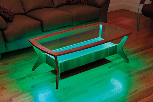
The coolest feature of my coffee table, though, is something that didn’t even exist in the 1950s: built-in LED lighting. A strip of colorful LED lights set into a channel on the underside of the glass frame casts a dramatic light that makes the whole table look like it’s glowing. A compact infrared (IR) remote control turns the lights on and off and allows you to select from a rainbow of colors and sequences that change colors gradually or abruptly. The remote sends signals to the light’s control module via a small, discreetly placed sensor eye. The lights are powered by a 12-volt sealed lead-acid battery (no power cord needed!) that keeps them lit for hours and can be recharged with a standard car battery charger. (Even if you don’t build this table, these LED strips are inexpensive and a great way to add lighting to all kinds of freestanding cabinets and furniture).
Making Templates
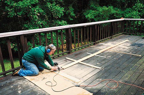
To make creating the coffee table’s curved legs and glass frame members easier and more accurate, I made templates for each part and then shaped them with a router.
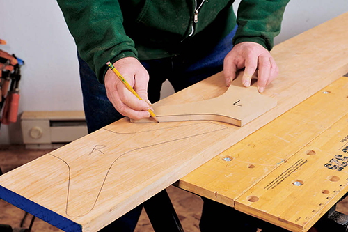
To create the template for the table’s legs, I transferred the design shown in the Drawing, onto a piece of 1/2″ MDF, then cut out the shape with the band saw. I cut just outside the marked lines, then carefully sanded the template to final shape using a benchtop disc sander and an oscillating spindle sander. I sanded until all the curved edges were smooth and flowing.
To make the curves of the templates for the table’s glass frame members perfectly regular, I routed them using a large circle jig. The shorter members have a 60″ radius and don’t pose much of a problem: I clamped a 22″ x 4″ piece of 1/2″ MDF stock to one end of my benchtop, and clamped a “pivot block” to the other end. I then set my circle jig to a 60″ radius and cut the template’s outer curve with a 1/4″ straight bit. To rout the template’s inner curve, I repositioned the pivot pin 3″ farther away from the stock. The final template ends up 2-3⁄4″ wide (the extra 1/4″ is to account for the diameter of the router bit).
The long glass frame template is more challenging, as its radius is a whopping 200″! I used the same procedure as with the short frame member; however, I created an extension for my circle jig from a couple of lengths of 5″ wide, 1/2″ plywood scabbed together. I cut the template starting with a 50″ x 5″ piece of 1/2″ MDF. I set up my giant circle jig out on my wood deck, the only space I had big enough for the job!
Making the Legs
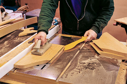
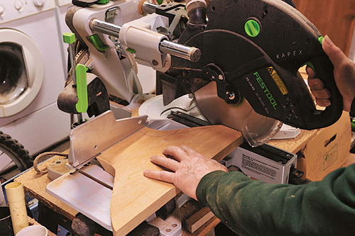
When it was time to shape the parts, I started with the legs. First, I laid out the legs on a length of 1″-thick cherry, tracing around the template to draw the outline of each leg. To save stock, and to make sure I’d end up with two pairs of left-hand and right-hand legs, I flipped the template over and aligned its straight edge first with one edge of the stock, then the other. I used a jigsaw to divide the stock into separate blanks, sawing well clear of the marked lines, and marked each blank with an “L” or an “R.” Then I set my table saw blade to precisely 45˚ and trimmed off the straight side (the part that will attach to the drawer box) of each leg at this angle. Moving to my compound miter saw, I trimmed the top edge of each blank square (where the leg attaches to the glass frame) relative to the 45˚ edge. Then I cut out the curved portions of each leg on the band saw, sawing just outside the marked template lines.
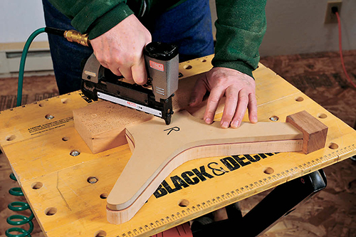
Back at the workbench, I carefully aligned a leg template to one of the blanks using a couple of scrap blocks to make sure that the top and side straight portions of the template and blank were flush, and then temporarily fixed it in place with a few fasteners driven with a pneumatic 23-gauge pin gun. You could use double-stick tape or adhesive transfer tape to attach the templates, but the pins hold it more securely and leave only tiny holes that are easily filled and end up nearly invisible.
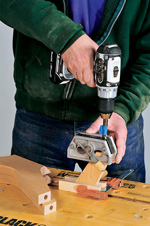
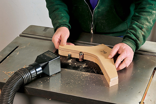
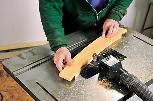
At the router table, I chucked up my sharpest, largest diameter piloted flush-trim bit and fit the table with a starter pin — a steel dowel mounted near the bit — to help stabilize the leg blank during freehand routing. With the router running at moderate speed (I set mine to #4 out of six speed settings),I routed around each leg, feeding the stock at a moderate speed from right to left (against the rotation of the bit), taking care to keep the pilot bearing in firm contact with the template. I avoided routing around the tip of the leg’s foot (the part that sits on the ground), as the bit could easily cause excessive tearout here or even catch and hurl the leg with some violence! With flush trimming done, I removed the template with a small putty knife, then used a benchtop disc sander to sand the foot area flush to the marked line. After pulling the pins out of the template, I repeated the routing process on the other three leg blanks. I then used a self-centering doweling jig as a guide to bore 1/2″ holes into the top end of each leg (for attaching the glass top later). I positioned the jig so that the holes end up about an inch from the outermost edge of the leg.
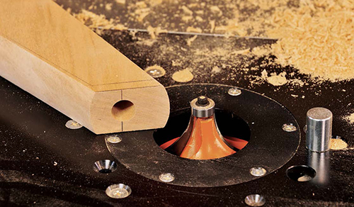
The next step is to give all the leg’s curved edges an oval-shaped “fingernail” profile. This subtle rounded profile is commonly found on the edges of many mid-century furniture pieces. Since I didn’t have a special “oval edge” or “half bullnose” bit to cut this profile, I routed the edges using the gently curving lower portion of a 1″ radius piloted roundover bit. After chucking the bit into my router table, I set its height with the bit’s pilot bearing roughly centered on the thickness of the leg. I routed around the curved portion of each leg, stopping short of the straight sections, first doing one side, then flipping the leg over and routing the other side. Just as with the template-routing process, I used a starter pin and worked very carefully when shaping around the leg’s pointy feet.
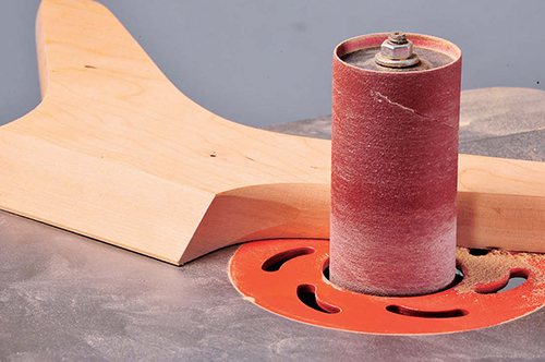
Using an oscillating spindle sander fitted with a 2″-dia. drum, I then “faired in” the oval profile shape where the curved sections intersect the angled portion of each leg. Finally, I sanded the legs smooth, using both an orbital sander and, on the curving edges, strips of sandpaper pulled back and forth “shoeshine” style.
Creating the Glass Frame
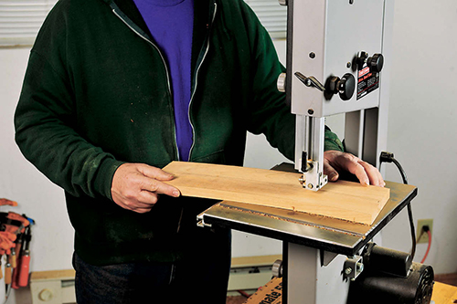
The template-routing process for shaping the coffee table’s glass frame starts with laying out the long and short members on a length of 4/4 stock, planed down to 13/16″ thick. Tracing around the curved templates, lay out two long and two short members. I cut these out on the band saw, cutting just outside the lines and leaving the ends untrimmed. I temporarily pinned the appropriate curved template to the underside of each member, then routed them to shape on the router table using the same flush-trim bit setup used previously for the legs.
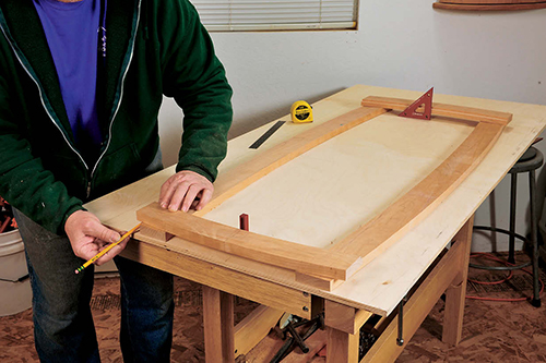
Instead of cutting the frame members to length, I used the long members themselves as a guide for trimming the ends of the short members to the correct length and shape. This is important, as the short members join the long ones along a curved joint line, so the ends must have the same radius curve as the long members. To assure that the top ends up square and symmetrical, I used a flat piece of plywood 4-1⁄2′ long and 2-1⁄2′ wide as a base on which to align the frame for trimming. First, I drew a 48″-long, 26″-wide rectangle on the plywood and marked the middle point of each side. I then set the two long frame members inside the rectangle, making sure their midpoints lined up. I drew the outline of each member onto the ply, then repositioned them so that their outer curves were aligned with the drawn inside curve lines. I set the short members atop the ends of the long ones, and aligned them to the rectangle until they were centered and even. With a pencil, I marked a line on the underside of the short members where they extended over the outer curve of the long members. After band-sawing off the excess, I repositioned and clamped each short member, then used a flush-trim bit in a router to trim the end of the short members flush.
Next, I cut the slots for the #20 plate joinery biscuits that join the frame members. With a 5/32″ slotting bit in the router table, I routed a slot in the end of each short member, stopping each cut 1/8″ shy of the edge, then routed matching slots on the inside edges of the long members. I glued up the frame, using cutoff scraps as clamping blocks.
Once the glue was dry, I scraped any excess glue from the frame, then routed a 3/8″-wide x 1/4″ rabbet (for the glass top) around the inside of the frame using a piloted rabbet bit and a router. I then used a sharp chisel to extend the inner edge of the rabbet cuts where they meet at the corners.
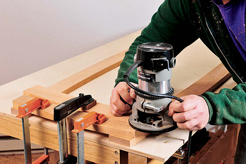
To trim the ends of the long frame members, I clamped the glass frame on top of the short frame template, set it flush and even with the short member below it, then used my flush-trim bit and router to trim the end curved.
Next, I routed a shallow channel on the underside of the frame for the LED lighting strip. I mounted a fence to my router fitted with a pair of lobes designed to ride on the curved outside edge of the frame to guide the cut. I chucked a 7/16″-dia. straight bit into my router and set it for a scant 1/8″-deep cut. With the fence adjusted to space the edge of the channel 5/16″ from the inner edge, I routed all the way around the frame.
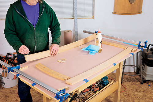
I also used the router to give all the outer frame edges the same “fingernail” profile as on the legs. Since the frame is thinner than the legs, I used a 3/4″-radius roundover bit set so that the pilot bearing rides just a hair below the center of the stock’s thickness. I routed the frame all the way around, first on one side, then the other. Finally, I sanded the entire frame smooth.
Building Drawer Box
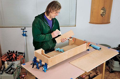
The coffee table’s four legs are connected at their midsection by a rectangular drawer box built from 1/2″ plywood. I cut out all the pieces needed for the box as specified in the Material List making sure that the grain direction of the plywood ran perpendicular to the length of the box’s back, front, drawer face and two front side pieces. Before assembling the box, I glued a 1/16″-thick-piece of cherry edge banding on the top edge and ends of the drawer front, the inside end of each front side (adjacent to the drawer opening) and the front edges of the top and bottom. After tacking on the two spacer strips to the front edges of the bottom (the top gets these, too), I glued on the ends, with the back and front pieces butting over the ends, as shown in the Drawing. I drove a few pneumatic pins into the parts, to keep them aligned, then clamped up the entire assembly and set it aside to let it dry.
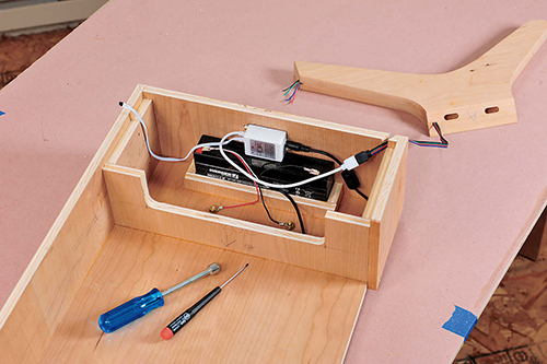
On the band saw, I cut out a U-shaped section from the top edge of the box’s right-hand bulkhead; this provides access to the lighting electronics. I glued the four corner blocks to the inside ends of the drawer box, and then glued in the two bulkheads and nailed it to the ends of the corner blocks. I also glued on the top brace strip and the three small plywood strips that form the battery box.
Adding the Drawer
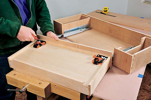
The coffee table’s drawer has sides all cut from 1/2″-thick solid maple. I used a dado blade in my table saw to plow a groove for the drawer’s 1/4″ maple ply bottom. The groove is 1/4″ deep and spaced 1/2″ up from the bottom edge of the drawer sides. To accommodate the special push-to-open glides, two notches were cut at the lower corners of the drawer back, as well as a couple of 1/4″- dia. holes, all positioned as shown in the Drawing detail.
I used blind dowels to join the front and back pieces to the sides of the drawer box. During assembly, the drawer bottom is captured in the groove. After clamping, I checked the squareness of the drawer by making sure the diagonal measurements were the same. After the glue dried, I installed the two plastic glide mounting clips on the underside of the drawer.
To mount the drawer, I first screwed the push-to-open glides to the drawer box bulkheads, setting the glides’ front edges back approximately 3/4″ from the front of the box. After clipping the drawer onto the glides and fine tuning its alignment, I clamped the cherry plywood drawer face onto the front of the drawer, adjusted the gaps at the sides and top (they all should be about 1/32″), then drilled and drove a few screws from the inside of the drawer into the back of the face to secure it in place.
Attaching the Legs
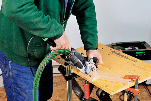
To create a strong joint between each leg and the drawer box, I decided to use two 8mm x 40mm loose tenons set into mortises created using Festool’s Domino machine. I first set the Domino’s fence to match the 45˚ angled side of the legs, then adjusted fence height so that the edge of the mortise was 5/16″ from the flat side of the leg. To assure accurate positioning of the tenons, I used the machine’s built-in, spring-loaded stops to space each mortise from the edge of the leg.
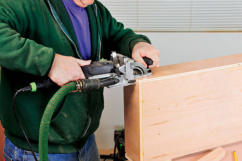
Next, I set up the Domino machine to cut matching mortises in the drawer box assembly. I set the machine’s fence at a 90˚ angle and adjusted the fence’s height so that each mortise was spaced 5/16″ from the corner of the drawer box. Using the machine’s built-in stop pins as before, I cut all of the eight mortises into the ends of the drawer box.
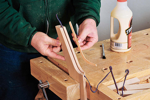
Before attaching the legs, I cut a slot into the upper inside edge of the righthand leg on the drawer front side for the wiring that connects the LED strip lights to the battery and control box. I did this using a 1/8″-wide slot cutter bit chucked in my router table. I fit the bit with a pilot bearing sized to create a 1/2″-deep slot. The height of the bit was set to center the cut on the thickness of the leg. The slot extends from the top of the leg to the angled joinery surface. Next, I cut a hockey stick-shaped filler strip from 1/8″ thick cherry. After carefully pressing the four-conductor wire into the slot, I glued the strip into the slot, waited for it to dry, then trimmed it flush with the edge of the leg.
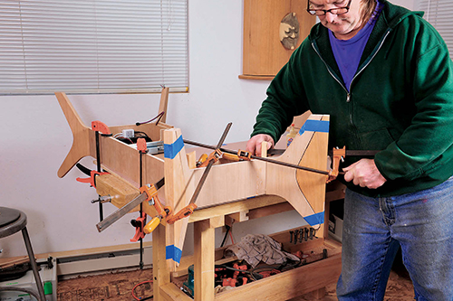
In preparation for gluing the legs to the drawer box, I taped on the scraps that were bandsawn off of the outside section of each leg, to serve as clamping cauls. I also placed the 45˚ cutoff scraps in the inside corners of the drawer box and clamped against these strips. After applying glue liberally to both the mortises and the Domino loose tenons, I pressed the legs into place one at a time, using a pair of small bar clamps to pull the angled surface of the leg flush with the end of the drawer box.
Installing the LED Lighting
Now is a good time to install all the components and wiring for the LED lighting. After slipping the battery into its shallow box, I screwed the control box just above it, so that it’s tight against the top of the battery to keep it in place. I then wired the components together, connecting both the four-conductor wire from the leg and the leads from the battery to the LED control box. I also connected two extra leads from the battery terminals to a pair of #10 x 1″ brass screws set through holes in the bottom of the drawer box. The screws were set up with nuts and washers so that they protruded from the bottom of the box. These act as terminals that allow you to easily recharge the battery without having to access the wiring inside the box (just be sure to set your automotive charger to its lowest amperage setting, e.g. two amps).
Before installing the LED light strip in the channel routed for it on the underside of the glass frame, I pre-finished the underside of the top with the same finish I used on the rest of the table and let the finish dry overnight. To get the light strip to go around the entire frame, it must be cut into four sections.
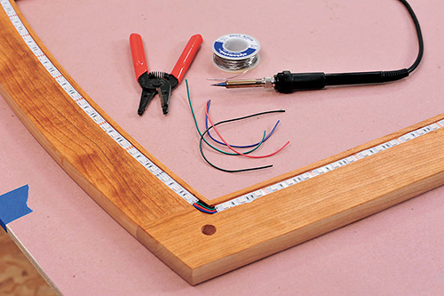
Fortunately, the LED strip is designed to be cut into segments as short as a few inches. Once they were cut to length, I peeled the paper backing off the PSA-backed strips and stuck them into the channels. Now comes the tedious part: soldering the four connections between the ends of adjacent strips to connect them together. The job is made easier by the fact that the places where the strips are cut have exposed copper patches made for soldered connections. The last connection, where the strips connect to the multi-strand wire that runs up the leg, is done after the table is fully assembled.
Final Assembly
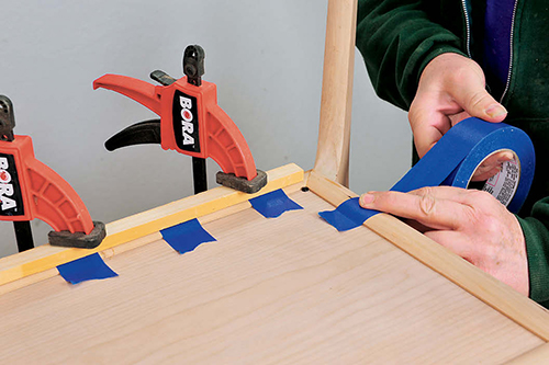
Before installing the top of the drawer box, I pressed the IR sensor for the LED lighting up into a 1/4″ hole drilled near the corner of the top. I then glued the top into place and secured it with a few nails at the corners, bulkheads and bracing strip. Next, I fitted and glued/nailed on the thumbnail-profile molding around the top of the box, cutting 45˚ miters in the corners where the moldings meet.
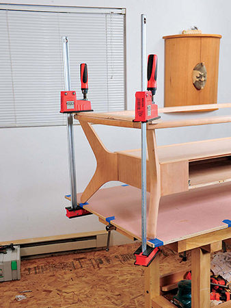
To attach the glass frame to the legs, I first slipped a pointed dowel center into the 1/2″ hole atop each leg, then set it onto the glass frame inverted atop the workbench. After carefully positioning the table and frame, I firmly pressed each leg down at the corner until the point of the dowel center made an impression. I drilled a hole at each mark using a 1/2″-dia. brad-point bit (take care to use a depth stop, lest you accidentally drill through the frame!). I applied glue into all holes and onto 1/2″ x 1-1⁄2″ fluted dowels, driving them first into the legs, then I set the top on and tapped it onto the dowels with a mallet. Clamps set between the glass frame and the leg’s feet drew the dowel joints tight.
After final sanding all parts down to 240-grit, I taped over the IR remote sensor and finished the piece with Danish oil. I allowed the finish to dry thoroughly, then I soldered the multi-strand wire (coming from the leg) to the end of the light strip. My final task was to install the 1/4″ glass top, cut by a local glass shop from a cardboard pattern I made by tracing around the rabbet in the frame. All that was left was to press a button on the LED remote control, sit back and enjoy a colorful light show.
Hard to Find Hardware
Salice Futura Push-to-Open Drawer Slides (1 pr.) #49616
Click Here to download a PDF of the related drawings.
