I was watching our big screen TV in the family room one evening when I started feeling a bit guilty for not working on an electronics project I have going. But I didn’t want to entirely abandon the movie, or leave the comfort of the couch.
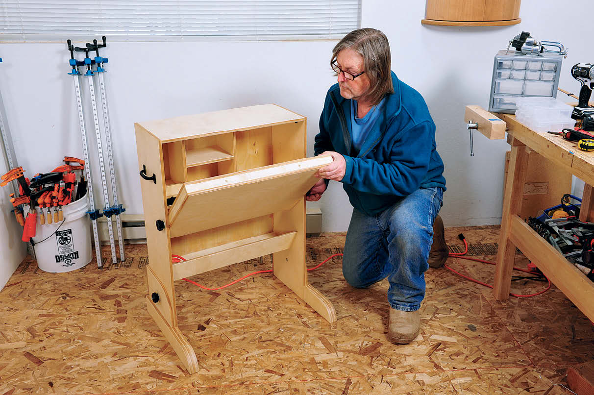
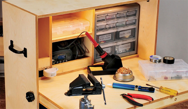
The solution came to me: Why not build a simple, portable hobby desk? My project has a fall-front style desktop, built with torsion box construction that flips down to provide a strong, ample work surface. The inside of the cabinet provides storage, and is concealed when the desktop is pivoted closed. A pair of legs keep the cantilevered desktop rock-solid.
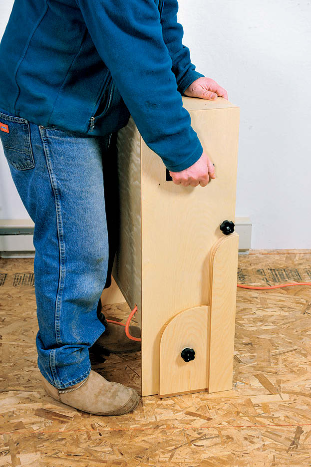
They can be rotated up to make the cabinet more compact. When it’s in use, the feet can slide partially underneath my couch. A pair of handles allow the folded-up desk (about 2′ wide, 3′ high and 1′ deep) to be easily carried. And, to make working at my new hobby desk easier on my aging eyes, I fitted a worklight on the underside of the top.
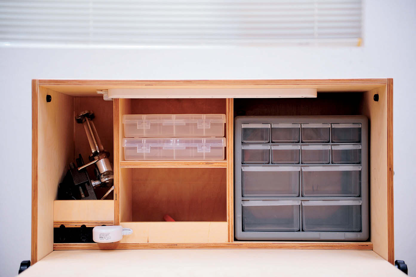
The inside layout of my desk is designed specifically to fit my needs for small electronic components, but you could rearrange the interior to work well for any number of other hobbies: tying fishing flies, building scale models, making or repairing jewelry, stamp, coin or rock collecting, rubber stamping, scrapbooking, etc.
I built the desk entirely out of Baltic birch plywood joined with plate joinery biscuits and left the ply’s edges exposed (a look I actually like), and was able to build the entire piece in just a few days. However, if you have more time and want a more attractive piece, you could build it from solid hardwoods, employ decorative joinery and fancier hardware — as you wish.
Cutting Out the Parts
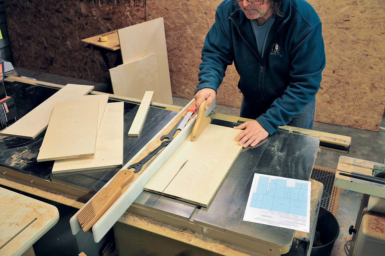
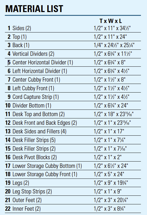
All the parts for the hobby desk are cut from a single 60″ x 60″ sheet of Baltic birch plywood. To get the maximum yield from the sheet, I used a free online panel optimization program (found here: http://www.optimalon.com/online_cut_optimizer.htm). I input the size of the parts and the plywood sheet, and it gave me a layout diagram that I followed during cutting. As with all cabinet projects, it’s not only important to get your part dimensions cut right on the money, but to make sure that all these rectangular parts are all nice and square (it saves a lot of fuss and bother later on).
Once all the parts are cut, there are a few more table saw operations to perform: The back, inner edges of the top and sides receive a 1/4″-wide by 1/4″-deep rabbet, for insetting the desk’s 1/4″ plywood back. I cut these with a regular dado set. I also cut a 1/8″-wide, 1/4″-deep channel centered on the back edge of the left-hand cubby divider (for routing the wire for the built-in light). Finally, I set the table saw’s blade at 30˚ to cut the slanted front edge of the lower cubby shelf and both long edges of this cubby’s front strip.
Cutting Biscuit Joinery
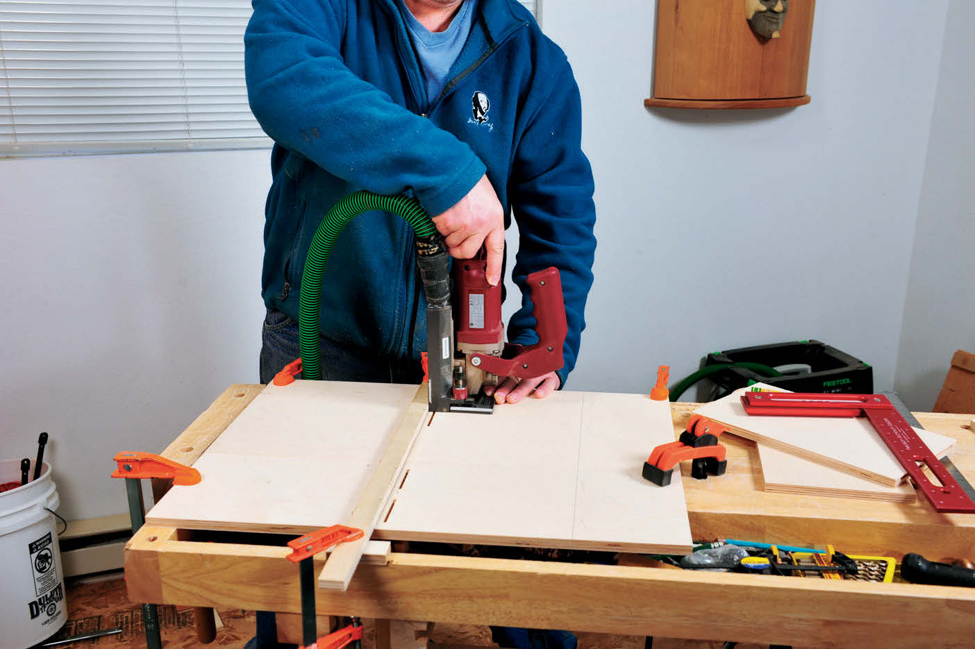
I used #10 plate joinery biscuits to create strong joints between the cabinet’s main plywood components. For the parts to align correctly during final assembly, it’s important to locate all the biscuit slots accurately.
To do this, I first clamped both of the cabinet’s sides to my benchtop with the inside faces up, ends flush and inner edges touching. I then carefully marked the location of the lower edges of the bottom and lower cubby pieces. I clamped a straight scrap strip atop the sides, with the strip’s edge flush with the line, marked the corresponding position of each biscuit slot on the two sides, then plunge-cut them. I then cut the slots into the ends of the corresponding parts, referencing the bottom of the biscuit joiner.
Making the Torsion Box Desktop
The top is basically a torsion box consisting of a top, a bottom, four edges and then a number of internal filler strips. I made the entire thing out of 1/2″ Baltic birch plywood, which makes the top incredibly sturdy, but also a bit heavy. I’d have used 3/8″ thick plywood, if I’d had any on hand.
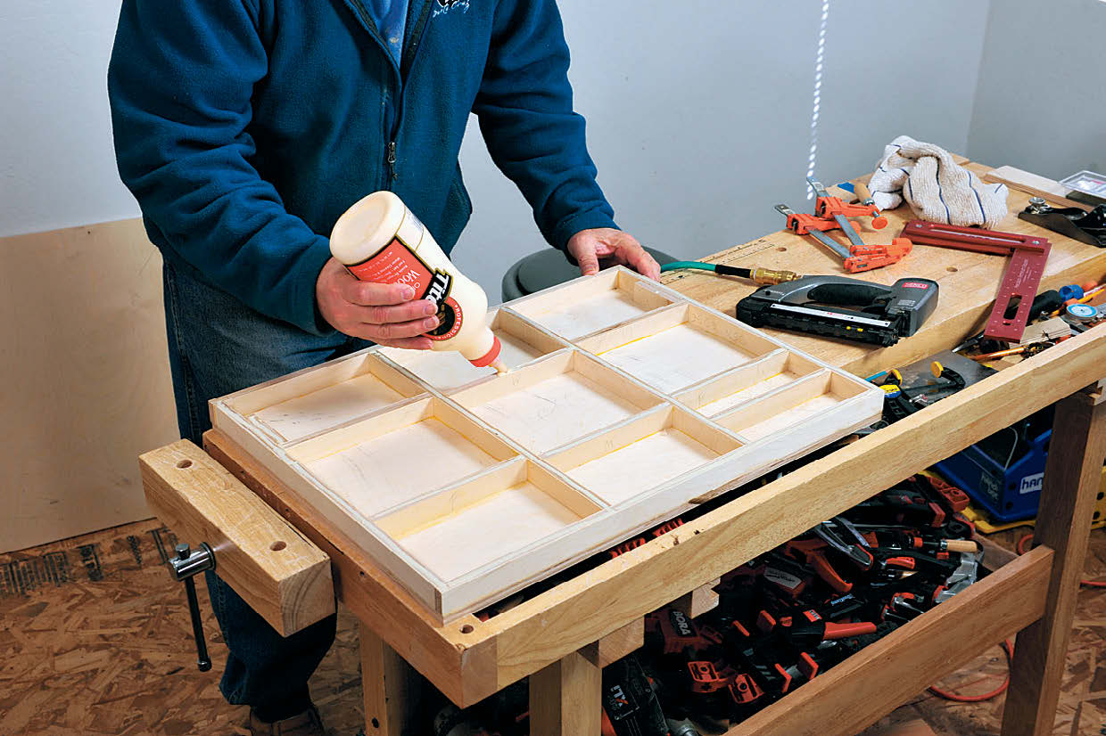
The first step is to glue all the edges to the bottom of the desktop, aligning their outer surfaces with the top’s edges. I glued on the long edge strips first, using my pneumatic pin nail gun to affix them, then trimmed the length of the short-side edge pieces to fit (necessary because plywood thickness tends to vary slightly). I next glued in all my filler strips: long ones crosswise, with the short ones interspersed between them. I added an extra short filler strip near the front left edge of the top, to reinforce the section where I’ll attach my clamp-on vise. I also glued in the two pivot blocks to the inside of the short edges, locating them where the hanger bolts that pivot the desktop will be added later.
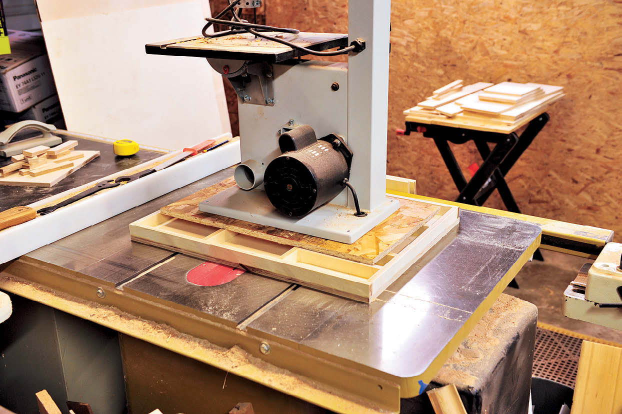
Once all the parts were glued in place, I set the entire assembly, bottom down, atop my most reliably flat surface: my cast-iron table saw top. I put a piece of scrap ply atop the assembly, then set the heaviest thing I could easily lift onto the plywood (in this case, that was a 10″ benchtop band saw). After the assembly dried, I applied glue to all the desktop’s edges and filler strips, then set the top piece of plywood on and drove a few pin nails to hold it in place. I clamped the entire top all the way around, using some deepthroat clamps to apply pressure closer to the center of the top as well as using regular clamps around the edges.
Constructing the Legs and Feet
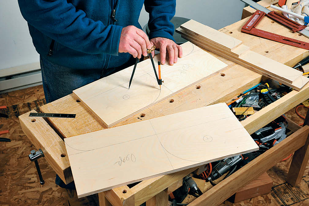
The legs were made in a series of steps. I first marked out the necessary cuts on the outsides of both of the larger leg pieces, including the 4-1/2″-radius curve on the upper corner and the 3″ radius curve on the end of the foot. After band sawing out these curves slightly outside the marked lines, I sanded the larger curve on the “knee” of the leg to final shape and size using a benchtop disc sander. I then glued the stop strip to the back edge of each leg piece, with the strip’s outside edge flush with the outside surface of the leg.
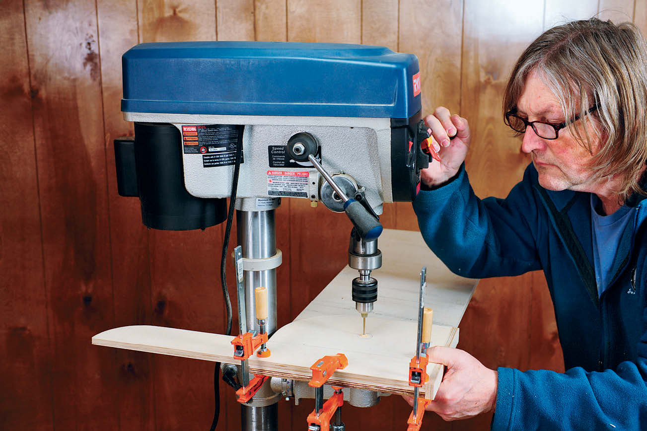
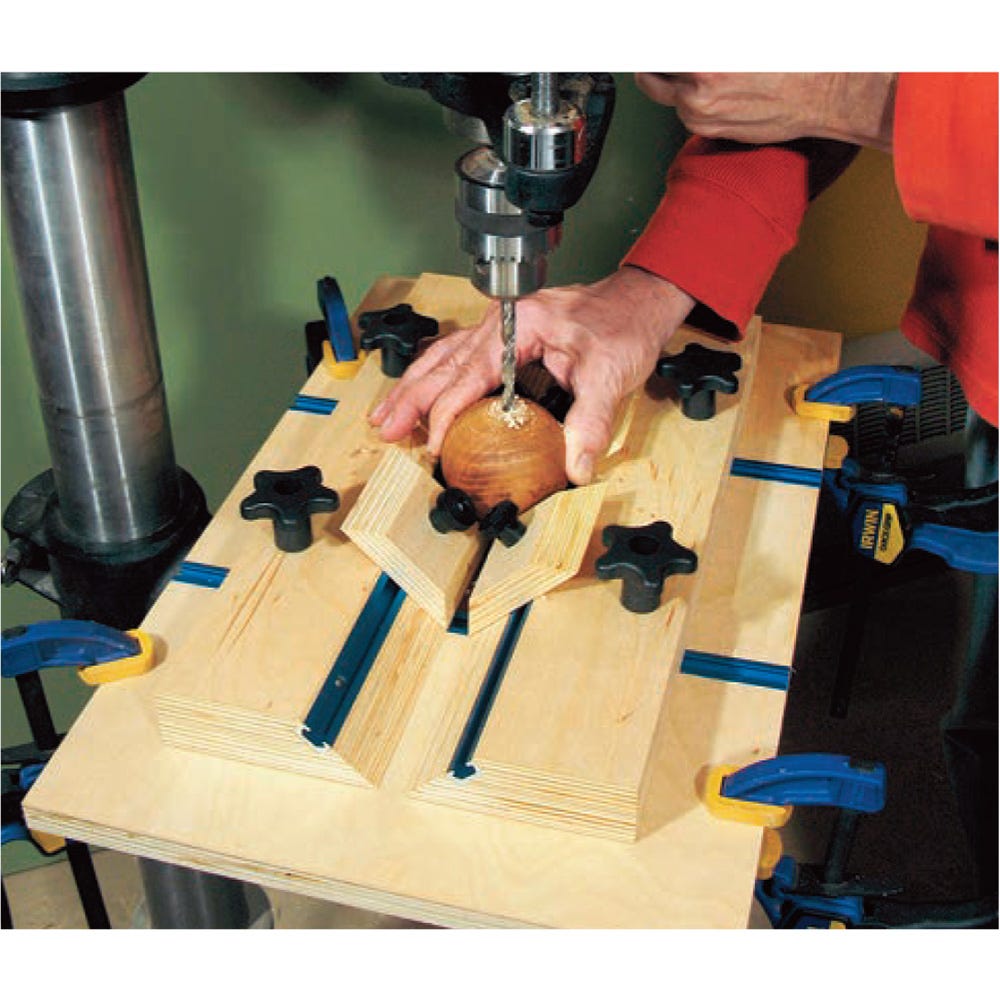
Next, I drilled the holes for the carriage bolts that join the legs to the sides. First, I assembled the pairs of legs and sides, setting each leg’s stop strip against the back edge of the side and the bottoms of the parts flush. After each pair was clamped together, I carefully centered the marked leg mounting hole under a 1/8″-dia. drill bit chucked in my drill press. I bored a hole all the way through both parts, then, without re-clamping them, switched to a 1/4″-dia. drill bit and bored all the way through the leg, but only halfway through the side. After unclamping the parts, I centered a 5/8″-dia. Forstner bit on the 1/8″ hole on the inside surface of the side, and drilled down about 1/8″ deep, to create a recess for the carriage bolt’s head. Then I flipped the side over, and finished drilling the 1/4″ hole from the top. I repeated the process with the other leg/side pair.
As long as I was working at the drill press, I went ahead and drilled the 5/16″ holes for the hanger bolts to attach the desktop to the sides. I set one side atop the other with inside surfaces touching, carefully aligned the ends and edges so they were flush, clamped them together, then drilled all the way through both pieces at once. I also bored two 3/8″ holes halfway through the inside surface of the left-hand divider for the LED light wiring, and a 1-1/4″ hole through the back for the power cord (all hole locations are shown in the Drawings).
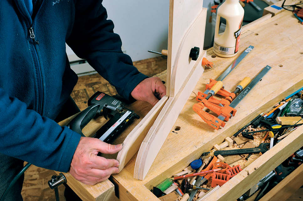
Back to the legs and feet: I shaped the curved end of each long foot. This became the template for shaping the other foot, as well as the foot portion of the legs. Once the pieces were sanded and ready, I glued the long foot to the outside surface of the leg, making sure its bottom edge was flush with the bottom of the leg. I then temporarily mounted each leg to its corresponding side, using a 1/4″ carriage bolt and threaded hand screw to hold it in place. Then I glued the shorter foot piece to the inside surface of the leg/foot, making sure its back edge was set flush against the front edge of the side.
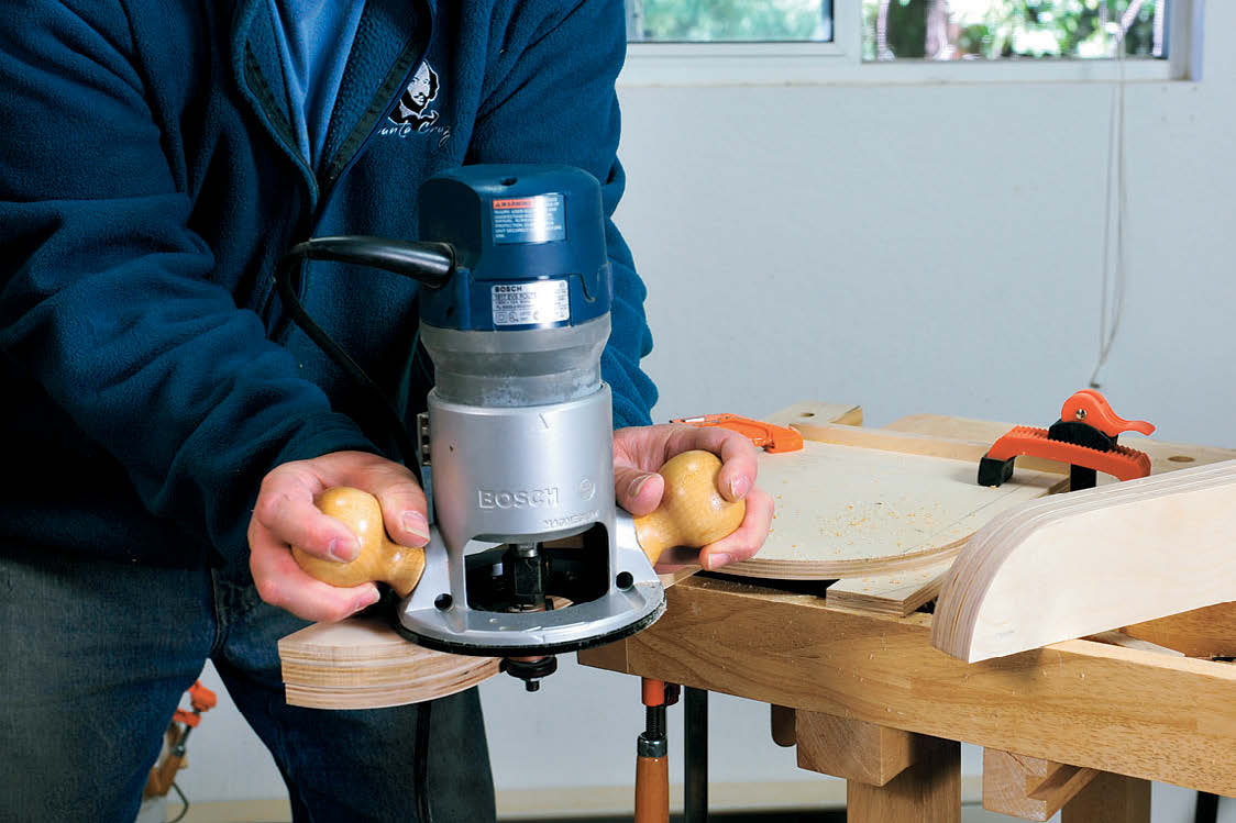
Once the glue was dry, I trimmed the feet to final shape using a flush-trim bit chucked into my router. I set the height of the bit so that the pilot bearing rode on the long foot piece. I clamped the leg onto my workbench so that the front edge of the leg was flush with the edge of the bench; this prevents the router bit from cutting into the upper portion of the leg. I then ran the bit along the top of the feet to trim them to final profile.
Fitting the Desktop
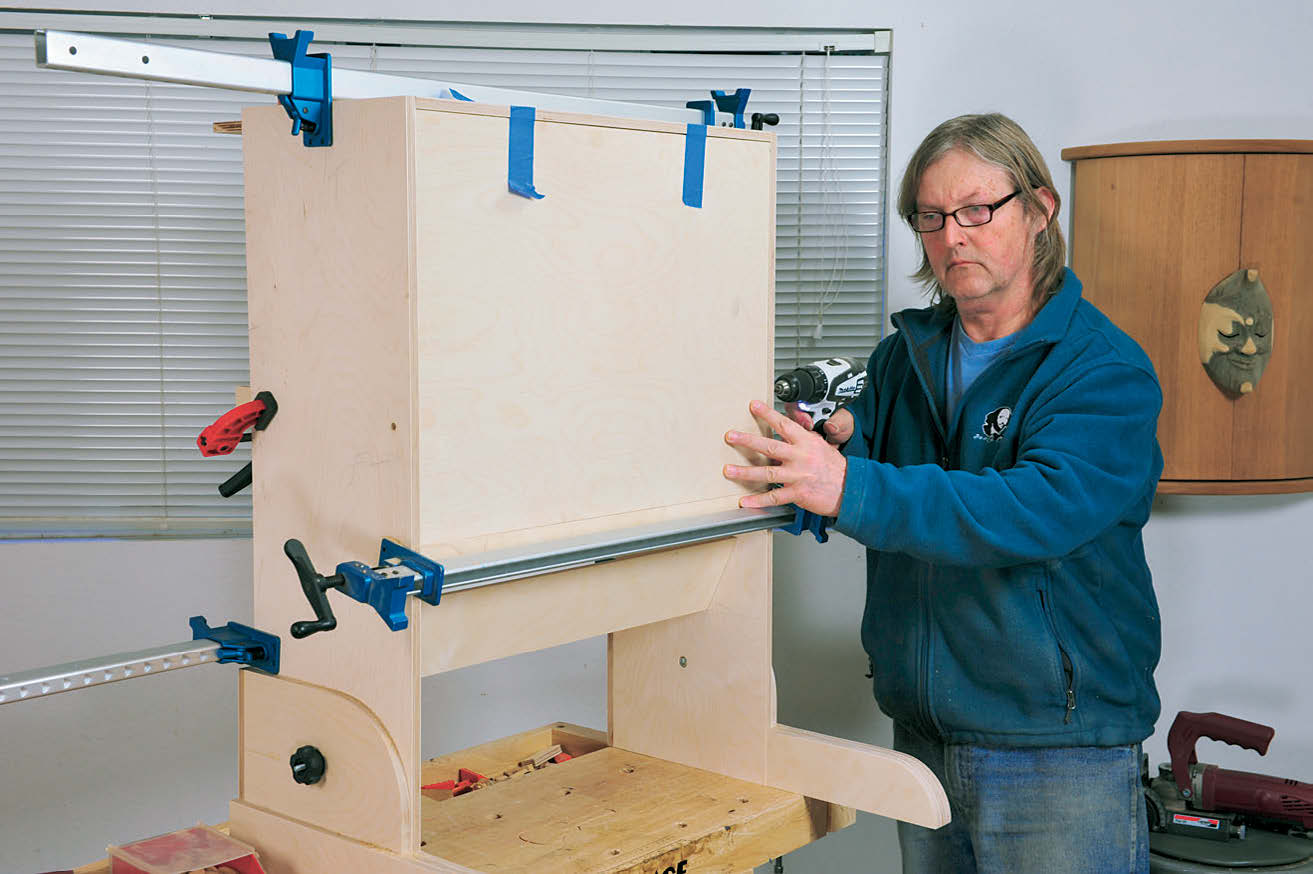
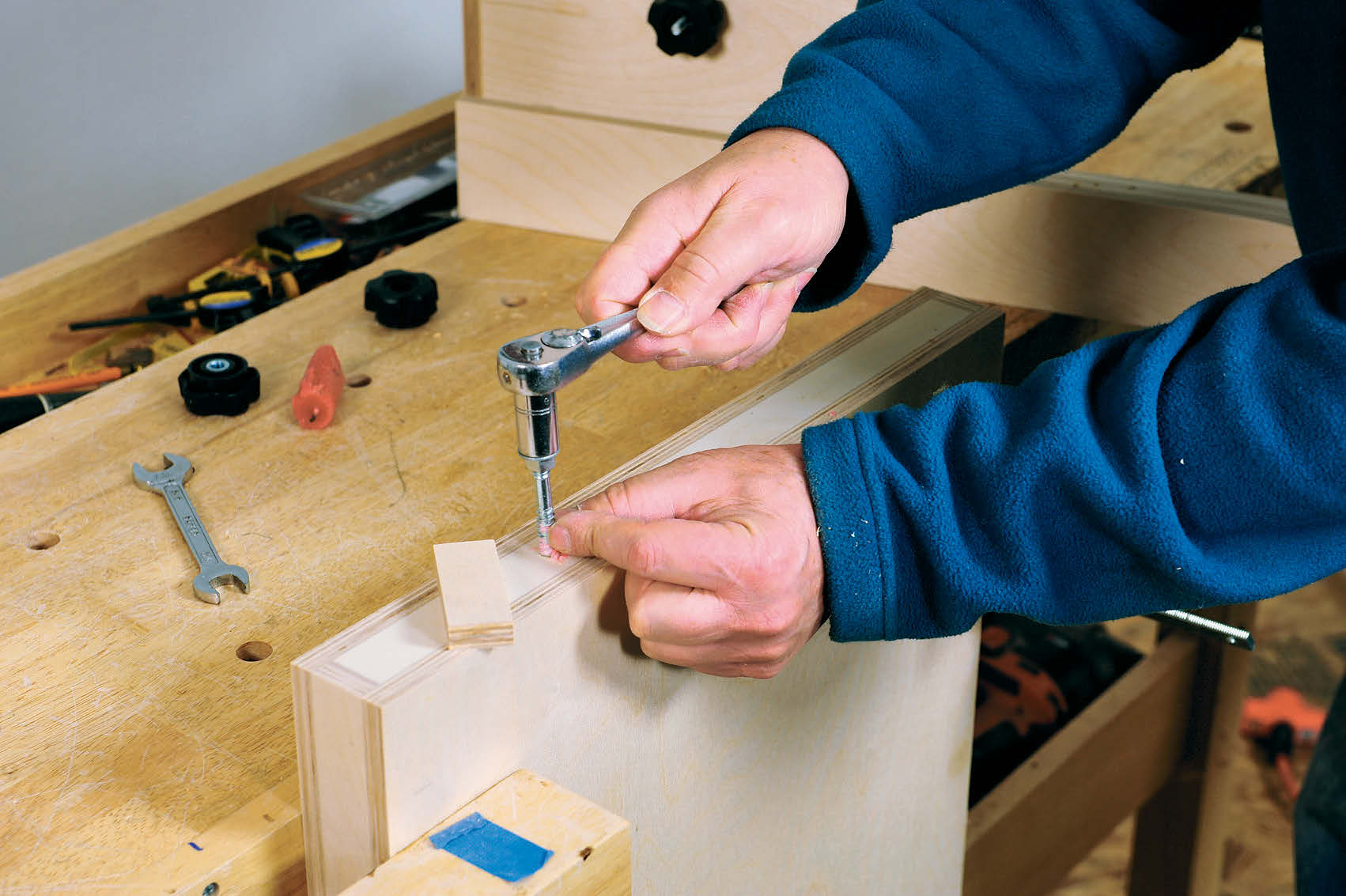
With all the parts sanded and ready for assembly, I needed to fit and mount the desktop into the cabinet before final assembly could commence. I dry-assembled the top, sides, bottom of the cubby and one vertical divider, and the lower cubby, using biscuits to align the parts as they were clamped together. To help align the desktop, I clamped four scrap strips to the sides, setting their ends 2-1/16″ shy of the front edge of the sides. I also clamped a strip across the front of the cabinet just high enough to support the desktop’s lower edge. I then set the top into the cabinet in its upright position, leaving a slight gap (about 1/16″) between its top edge and the cabinet. Once the desktop was aligned, I secured it with a clamp across the width of the cabinet. Then I drilled horizontally into the sides of the top with a 1/4″ bit, centering the bit in the hanger bolt holes drilled earlier. After this, I removed the top, clamped it to my workbench and installed the two 5/16″ hanger bolts. To drive them, I jammed two nuts against one another on the bolt’s regular threaded section, and used a socket wrench to run the screw part of the bolt into the desktop holes.
I reinstalled the desktop into the dry clamped cabinet, to make sure that it pivoted freely. This is a good time to drill two 3/8″ holes into the desk’s top edge, and install a pair of bullet catches that help secure the desktop in its closed position.
Glue-up and Finishing
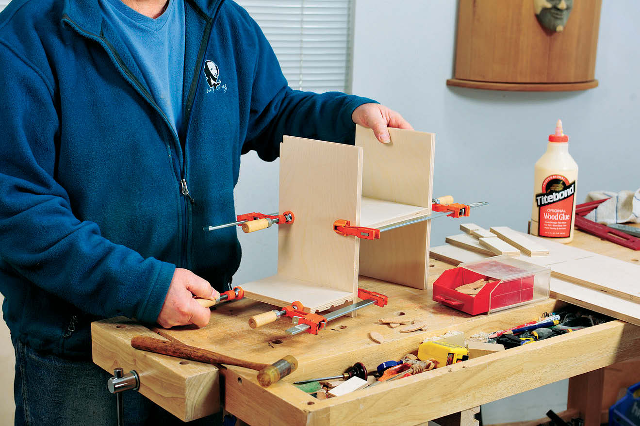
To make gluing up the hobby desk easier, I did it in several steps. The first step was joining all the parts that make up the divided cubbies inside the desk. I started by assembling the central shelf between the two vertical dividers, as well as the shorter shelf to the left-hand vertical divider, making sure to keep all edges flush and square to one another. After about half an hour, I removed the clamps and scraped the rubbery glue residue from all the inside corners of the parts. I used both a regular bench chisel and a short blade removed from a hand plane (to get into the tighter spaces between dividers).
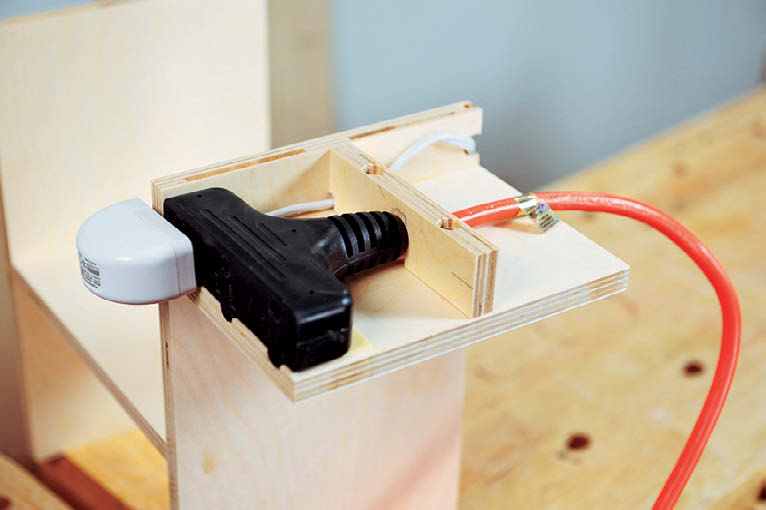
Because I chose to incorporate a power cord and LED light into the upper cubby unit, I then did a little carving using a Dremel tool fitted with a burr. I ground notches into the lower edge at the front of the short shelf to accommodate the three lugs on the top of the plug. I also used the burr to grind a small channel into the divider, so I could pass the wire from the light’s transformer past the plug. I then mounted the plug to the underside of the short shelf with a couple of pieces of mounting tape and screwed on the notched cord capture strip that secures the back of the power cord. With the power cord and light transformer in place, I glued the cabinet’s top and bottom to the cubby assembly, once again using plate joinery biscuits and checking the assembly for square after clamping. This is also a good time to glue together the two pieces that form the lower shelf. Once the glue dried and I removed any residue, I sanded smooth all the plywood edges, as well as any surfaces that still needed it.
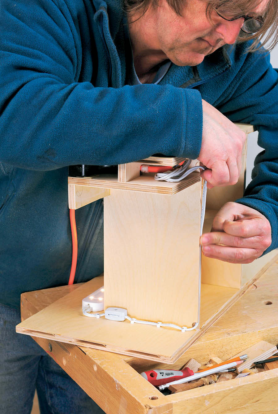
Before gluing up any more parts, it was time to apply finish to the upper and lower cubby assemblies, the legs/feet, the desk’s top, and the inside surfaces of the cabinet sides. To keep the finish out of the biscuit slots, I taped over them on the sides and tried to avoid getting finish on the ends of the cubby assemblies. After the finish dried, I removed the tape from the sides, then finished installing the LED light and its wiring in the upper cubby.
Completing the Project
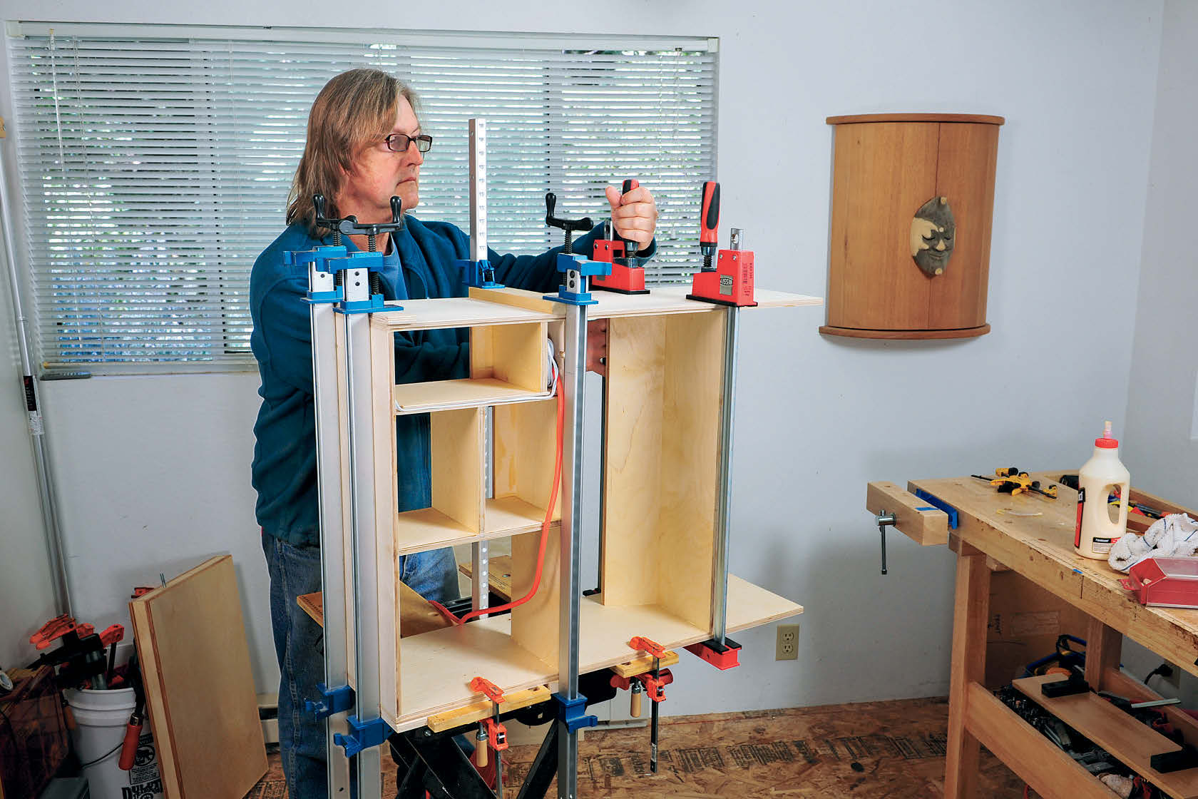
Final assembly also took place in two stages: first, the upper and lower cubbies were glued to only one of the sides; then the desk’s top was installed and the second side glued on.
In preparation for the first step, I clamped one cabinet side atop my portable work table and laid out all the clamps and clamping blocks I’d need, ready to go. I then glued all the biscuits in and put the cubbies in place. Before the clamps went on, I put dry biscuits into the end of the cubbies and set the other cabinet side on, as this helped to keep the parts aligned. I put clamps in place and tightened them enough to snug things up, then I checked the assembly for square, and tweaked it as necessary.
Once this assembly was dry, I cleaned up the glue residue, then installed the desk’s top into its pivot holes before gluing the other cabinet side in place. After that dried and was cleaned up, I final-sanded the cabinet’s top corners, then finished them with wipe-on polyurethane.
Before gluing and nailing on the back, I installed the two small rubber bumpers that provide stops for the desktop when it’s in the closed position. Last details included screwing on the two side handles, attaching the legs, and, of course, loading the inside of the cubbies with the part bins and trays, as well as small tools and supplies.
When I’m ready to use my hobby desk, I feed the power cord (which stores nicely in the lower cubby) through the hole in the back and plug it in. After lowering the desktop and turning on the light, I’m ready to work on my latest project while simultaneously indulging in my latest televised guilty pleasure.
Click Here to download a PDF of the related drawings.
