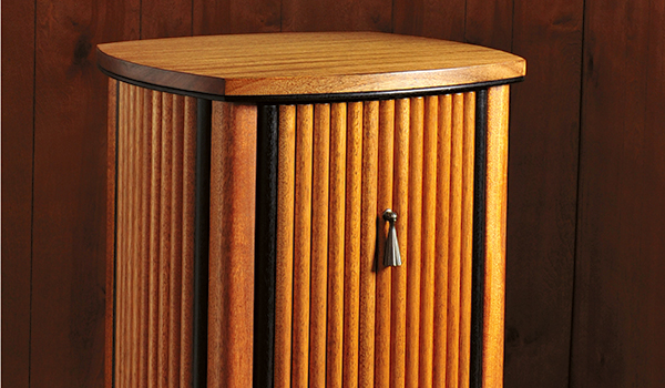
I’ve always loved the Art Deco style, whether it’s used in architecture, jewelry, tool design or furniture. So when it came time for me to build a new bedside cabinet last winter, I decided to create a piece in that style. The design I came up with, shown in the photos and Drawings, has the geometric lines and simple elegance of a classic Deco piece, yet employs modern functionality: instead of having a drawer or door, the cabinet features the kind of sliding pullout often used in modern kitchen cabinets. The pullout’s double-decker arrangement offers easy access to both a shallow top tray as well as a deeper lower cubby.
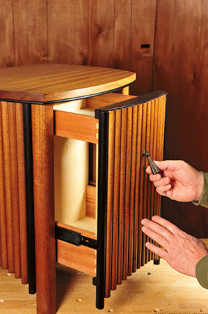
To create the cabinet’s curved sides, I came up with a construction technique that uses half-round slats connected together with tongue-and-groove joints. The joints allow the slats to follow the curved frame rails and let them expand and contract in response to changes in room humidity. Ebonized slats at the outer edges of each curved panel and ebonized trim bordering the underside of the top lend the cabinet a graphic element and a classic Art Deco motif.
Although originally intended as a bedside cabinet, I could also see this cabinet being used as an end table/cabinet at the end of a couch in the den, or as a freestanding cabinet in a living room or entryway.
Cutting and Shaping the Rails
The frame of my Deco cabinet is built much like any other basic cabinet, with rails that attach to the legs via loose tenon and dowel joinery. The side and back rails are “L” shaped in cross-section and are made up of two pieces: a straight piece and a piece that’s curved along one edge. The curved rail edges face out and support the slats which form the curved outer surfaces of the cabinet. The rails for the front of the cabinet’s pullout also have a curved edge, but no “L” shape; the two front rails and two rails that support the pullout’s metal drawer slides are straight.
After cutting out the stock for all the rail members and cutting them to final length as per the Material List, I used a beam compass fitted with a sharp pencil to mark the correct radius on each curved rail member: 14″ on the shorter side rails; 22″ on the longer back and front rails. Before marking, I set the compass’s pivot point square to the centerline of each rail member. I then rough-cut all the curves on the band saw, cutting about 1/16″ outside of the compass lines.
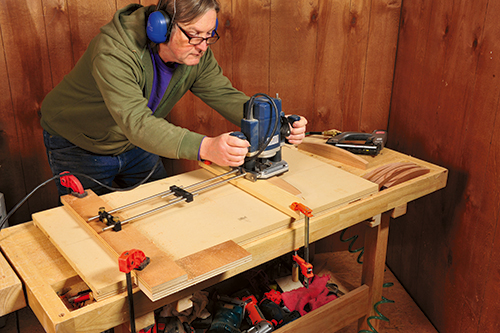
To assure a perfect radius, I used a router jig setup to trim the curved edges to final shape. The setup consists of a plunge router fitted with a 1/2″ spiral-fluted straight bit. It’s important to use a spiral-fluted bit, as part of each cut runs against the wood grain and a straight-fluted bit is likely to cause a lot of tearout. Attach a circle jig to the router’s base (I used a Micro Fence jig, but any circle jig will do). To make radius routing easier, I used an 18″ x 36″ scrap piece of MDF with a centered line drawn down the middle as a base plate. Near one end, I fastened a 3/4″-thick stop strip perpendicular to the line. The rails butt up to the board. I used another 3/4″ scrap with a centered hole drilled to fit the circle jig’s center point as a pivot strip.
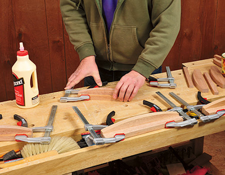
To complete the four side and two back rails, I glued each straight strip to the face of the corresponding rail, with the strip’s edge flush with the rail’s straight edge. The resulting “L” shape provides enough stock thickness for the joinery that attaches the rails to the legs.
You need two more steps to complete the side and back rails: One is to cut a 1/4″ x 1/4″ slot along the inside-facing edge on all four of the rails that form the top of the cabinet frame. These slots are for the wood cleats that hold the cabinet’s top to the frame, yet allow the solid wood top to expand and contract. I cut the slots on the router table, positioning them 1/4″ from the top edge of each rail. The other step is to plunge-cut slots for plate biscuit joinery that join the four rails at the bottom of the frame to the cabinet’s plywood bottom. One #20 biscuit centered on each side of the bottom provides enough strength and will help keep parts aligned during assembly.
Making the Legs
I cut the legs out of 8/4 stock, using the same kind of wood (mahogany) I used for the rest of the carcass. After planing the stock down to 1-5⁄8″ thickness and trimming it to final length, I jointed the edge square and ripped the four square legs on the table saw. Each leg is then rounded over on three of its four edges. The outer-facing edge receives a 3/4″ radius from a big roundover bit, a task done on the router table in two passes. For the first pass, I set the fence and bit height just shy of a full-radius cut. I then raised the bit to cut at full radius on the second pass, resulting in a chatter- and tearout-free surface. Next, I routed the two edges of each leg adjacent to the 3/4″ radius with a piloted 3/8″ roundover bit chucked in a freehand router.
Cutting the Joinery
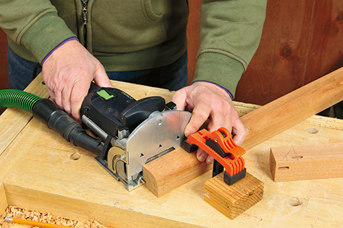
Since I’m lucky enough to own one of Festool’s DF 500 joinery machines, I used Domino loose tenons to join the legs to the side, drawer and back rails. The location of the pieces is shown on the Drawing. Notice that the mortises in the back rails are offset relative to those on the side rails, so they don’t run into each other on the legs. Once I’d marked the centerline of each mortise on the stock, I plunge-cut them in the ends of all the rails. I clamped each rail to my benchtop with its curved edge facing up. A square scrap of plywood clamped next to the rail helps keep the Domino machine square to the ends of the narrow rails. Next, I cut all the corresponding mortises into the inside facing surfaces of the legs, always making sure to keep the leg and Domino machine flat on the benchtop. Note that the two front rails don’t get mortised; these get doweled later on.
Frame Assembly
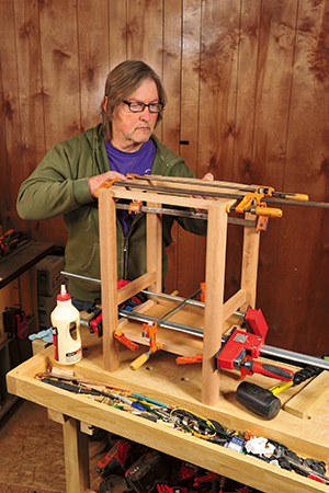
The Deco cabinet’s frame is glued up in two stages. In the first subassembly, the side rails and drawer slides are joined to a pair of front and rear legs. Before gluing up, I checked the fit and alignment of all the rail-to-leg joints using a small “test” tenon I made by shortening and sanding down the thickness of a Domino, so it could be inserted and removed easily. All the rails should align to the legs with their inside-facing sides flush with the square inside corner of the legs. I reworked any of the mortises that needed it. After spreading glue in all the mortises and on the Domino tenons, I inserted the tenons into the rails first, then fit the rail tenons into their corresponding leg mortises. I pressed or pounded everything together as needed, then applied clamps and allowed the subassembly to dry overnight.
Once the two side subassemblies were done, I created dowel joints for the two front rails that connect them to the side assemblies. First, I used a self-centering dowel jig to drill 3/8″ holes in the ends of both front rails, centered width-wise. Next, I drilled the corresponding dowel holes in side assemblies on the drill press, positioning the holes 17⁄16″ from the front of the leg.
When all was ready, I completed the assembly of the cabinet frame, first gluing the lower front and back rails to the cabinet bottom with plate joinery biscuits. I then applied glue to all the loose tenons and mortises or dowels and holes, and joined the subassemblies together, carefully applying clamps so as not to dent the outer surfaces of the legs or rails. Before leaving the assembly to dry, I checked to make sure all the top rails were flush with the ends of the legs, and that the entire frame was square. I also glued on the two little drawer stop strips to the inside-facing surfaces of the front legs, with their top ends butted up to the underside of the lower front rail.
Making the Top
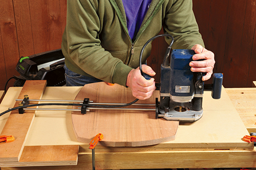
For the top of the Art Deco cabinet, I glued up enough narrower boards to make up the top’s 16-1/4″ width. When the glue dried, I scraped off the excess and ran the piece through a planer set to 3/4″, the top’s final thickness. I shaped all four of the top’s curved edges following the same process used to shape the curved rails earlier, first using a beam compass to mark the radii on the short and long sides (15-1/2″ and 23-1/2″, respectively). After band sawing the curves to rough shape, I used a plunge router and circle jig setup to trim the top’s edges to final shape.
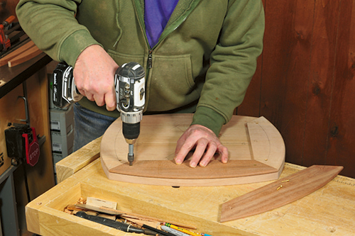
To give the top more thickness and help to better integrate it with the Deco design, I added a trim piece along its lower edge. Four 5/16″-thick pieces make up this trim, each mitered and screwed to the underside of the top to form a frame. To prevent expansion/contraction problems, I cut the two shorter trim pieces with the grain running across the length of the piece, so it runs parallel to the top’s grain. After cutting the parts to rough width, I mitered both ends of each piece at 45°. When assembled, the members should meet with their tips exactly at the junctures of the top’s curves. After rough-cutting the trim’s curved outer edges, I attached them to the underside of the top with small countersunk screws. I then used a spiral-fluted flush-trim bit in a handheld router to trim them flush with the top. After removing the trim pieces, I shaped both sides of each curved edge with a 1/8″-radius roundover bit to form a half-round profile.
Building the Pullout
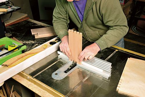
One of the most unusual and practical features of my cabinet is its pullout style drawer that slides on over-travel slides which provide full access to upper and lower compartments. It’s constructed from two pairs of 1/2″-thick solid wood drawer sides joined to a 1/2″ Baltic birch plywood front and back via box joints. I cut the joints with a dado blade in the table saw using a commercial box joint jig, but you can cut them on the router table or with any other shop-made setup you prefer.
I started by cutting out all the drawer parts, leaving the length of the sides and the width of the front and back just a scant 1/16″ over their final dimensions. The idea is that cutting the sockets a hair deeper than the stock thickness leaves the pins on the assembled parts slightly proud of the surface, so they’re easier to sand flush. I set my box joint jig to cut 1/2″-wide pins and sockets, then cut joints on both ends of all the drawer sides, starting with a full pin on the top edge of the shallow drawer sides, and a full pin on the bottom edge of the wider drawer sides. I then cut the necessary number of pins and sockets into the side edges of the plywood front and back.
Using the table saw, I cut a 7/32″-wide, 1/4″-deep slot about 3/16″ up from the bottom of each drawer side for a 1/4″ plywood bottom (hardwood plywood is always thinner than its stated thickness). I then cut the corresponding slots on the inside faces of the front and back pieces.
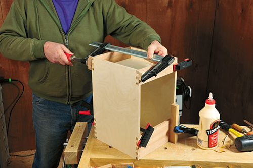
Once all the inside surfaces of the parts were sanded, I assembled the pullout in two stages, first gluing one pair of upper and lower sides to the front, and then the other pair to the back (just make sure to create a symmetrical pair). After clamping,
I checked to make sure all parts were square to each other before setting them aside to dry. I then glued the subassemblies together, making sure everything was square and true.
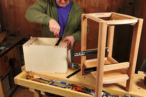
After the clamps came off, I used a belt sander fitted with a 100-grit belt to sand the protruding pins flat on all sides of the pullout. I then glued on the front rails to the top and bottom edges of the pullout front, centering them with their back edges flush to the inside face of the plywood. I also cut and shaped the pullout’s top cap from a 1/8″ thick piece of mahogany. It is shaped to a radius of 22-3⁄4″ on its forward edge.
Fitting the Drawer Slides
The next task is attaching the drawer guides to the cabinet frame and the pullout. I started by separating each slide into its narrower inner and wider outer components. Then I marked a parallel centerline that’s 31-3⁄16″ up from the cabinet’s bottom on the inside face of both drawer rails. The outer slide components were centered on this line, with their front ends 9/16″ back from the front of the legs. I screwed them on using the slide’s horizontally slotted holes. Next, I marked lines on the lower sides of the pullout that were parallel to and 3-5⁄8″ up from the pullout’s bottom. I centered the inner slides on these lines, ends flush with the front of the pullout, and screwed them on using the vertically slotted holes. I inserted the pullout into the cabinet, mating the drawer slides, and checked alignment. The back edges of the pullout’s curved rails should be level to and just make contact with the frame’s front rails. After adjusting the fit as needed, I installed screws into the round holes on all slide components to fix the hardware in place.
Shaping the Slats
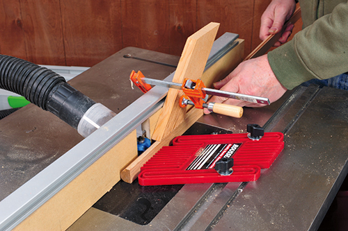
Regardless of the kind of wood the cabinet is built out of, the stock for the slats must be straight-grained and dead flat. If it isn’t, there’ll be problems during the shaping process that likely will result in a lot of twisted, unusable slats. I started by planing the slat stock down to the necessary 11/16″ thickness, then ripped it into 15/16″-wide strips on the table saw. I cut enough stock to make several extra slats, both for test cuts and so that I could discard any slats that weren’t up to snuff.
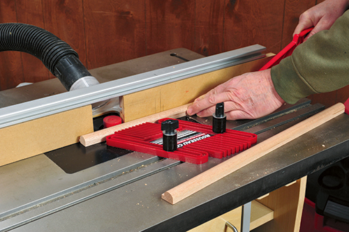
The majority of slats are shaped in three passes on the router table using three separate router bits. The first bit I used is a 3/8″-radius bullnose bit. This creates a half-round shape on the face of the slat. I set the bit’s cutting height so that the bottom of the radius was just flush with the edge of the slat and set the table’s fence flush with the deepest part of the bit’s half-round radius. A featherboard attached to the router table’s miter slot helped keep the stock flat against the fence as I ran the slats through. It’s important to feed each piece of slat stock smoothly and consistently, so the cut surface comes out clean and free of chatter marks; this saves a lot of sanding time later on.
The next step is to rout a small tongue in the lower lipped edge of the slats using a reversible glue joint bit. Set the bit height so that the lower edge of the tongue is formed 5/64″ above the bottom of the slat. (See the Drawings.)
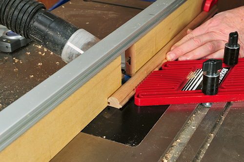
The final step is cutting the groove for the tongue on the opposite side of most of the slats with a 5/32″ three-wing slotting cutter. Two of the slats are set aside un-grooved, to be used as edge slats for the cabinet’s pullout front. I set the cutting height of the slotting cutter so the bottom of the groove is 7/64″ above the bottom of the slat, and set the fence for a 5/32″-deep cut.
After this step, I took four slats to the table saw and cut off their tongues, so that each ends up 3/4″ wide. Returning to the router table, I cut a groove into the trimmed side. These double-grooved middle slats will slide into place in the center of each slat panel.
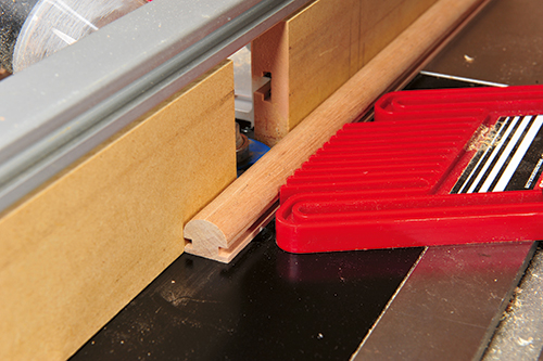
Finally, I picked six of the regular slats as edge slats for the cabinet’s sides and back. After resetting the cutting height of the slotting bit flush with the router table, I re-routed the grooved side of these slats, transforming the groove into a rabbet. The rabbeted edges lap over the edge strips at the outer edges of the panels on the cabinet’s sides and back.
From there, I carried the pile of slats to the miter saw, having marked the number and length of each one according to the edge strips, ripping and beveling them on the table saw.
Trial-fitting the Slats
When all the slats and edge strips were done, I did a quick test to see how well the slats fit onto their respective curved rails. Starting with the cabinet’s back, I set the edge strips in place, then set one of the rabbeted edge slats over it, tongue pointed toward the center of the panel. I then assembled the slats in order according to their length, finally sliding the middle strip onto the tongues of the two adjacent slats. The fit between the tongues and grooves should have just a little side-to-side play, and the gaps between the half-round slats should appear even and parallel. If the fit was tight, I used a thin block covered with sandpaper to enlarge the grooves as necessary. Once the fit was acceptable, I set all the slats flush to the top rail and trimmed off the short tongues on adjacent slats flush around the panel’s bottom curve. I repeated this entire process for the slats on the two sides of the cabinet. For the pullout, I lined up the edge slats with the ends of the front rails and temporarily clamped them in place before trial-fitting the rest of the curved panel.
To mount the cabinet’s pendant-style pull, I drilled a 5/32″ hole 5-1⁄4″ down from the top of the pullout’s middle slat. (The pull is the P3202-WOA Adorno, from knobsandhardware.com.) I enlarged the upper part of the hole slightly with a narrow chisel, to accommodate the pull’s squarish base.
Finishing the Parts
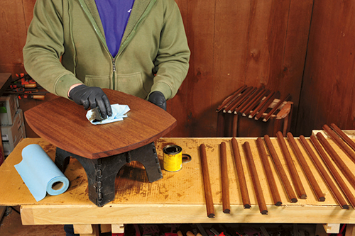
It’s most practical to finish the slats, top, pullout and cabinet frame separately before their final assembly. I sanded all the parts in three stages, using 120- and 180-grit paper and finishing with 240-grit. Since the mahogany I used for the project was so light in color, I decided to stain it with a light brown stain (Minwax® Provincial) to make it look darker and richer.
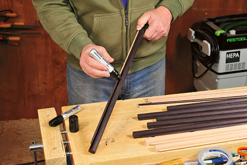
Next, I ebonized the parts that give the cabinet its graphic Deco look: the eight edge slats, six edge strips, the under-top trim, and the pullout’s top cap. In the past, I’ve used various black dyes to ebonize wood, but I’ve discovered that a black permanent marker pen provides an easier way to do smaller parts. The ink in these pens does a great job of making even light-colored woods jet black, and once dry, it’ll take just about any finish. After staining and ebonizing, I clear-finished all the parts with a wipe-on satin polyurethane.
Final Assembly
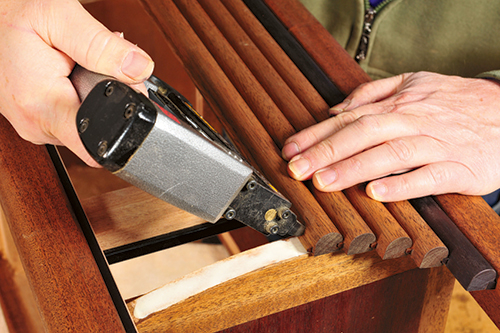
The final steps for completing the cabinet are attaching the slats and fastening the top. With the cabinet lying on a towel on the benchtop, I started by nailing the two ebonized edge strips to the insides of the legs at the back and sides of the cabinet using a pneumatic pin nailer. Then I applied the slats to the sides and back. Doing one curved panel at a time, I spread glue on both curved frame rails, then laid the slats on in order, making sure the top end of each was flush with the top rail.
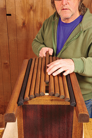
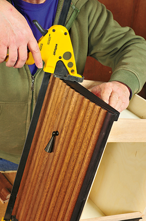
One by one, I fastened each slat to both curved rails by shooting a 23-gauge pin through the tongue portion.- With all the other slats in place, I slid in the middle slat and toe-nailed it to the rails at both ends with pin nails. On the pullout, I applied the glue to the rails, clamped the ebonized edge slats on with their edges flush to the ends of the rails, then fastened them by pin-nailing through the back of each rail. I attached the remaining slats as I did before. At this point, you can glue and pin the top cap that covers the slat joinery to the pullout’s top rail.
After screwing the ebonized trim pieces to the bottom of the top, I set the top upside down over a towel on the workbench and centered the inverted cabinet onto it. I set the four cleats into their rail grooves, one on each side, then screwed them to the underside of the top. All that remained was to flip the cabinet over and slide the pullout into place.
As I said at the beginning, this cabinet will fit right into a variety of room situations, and its Deco styling will add a special retro flair.
Click Here to download a PDF of the related drawings and Materials List.
