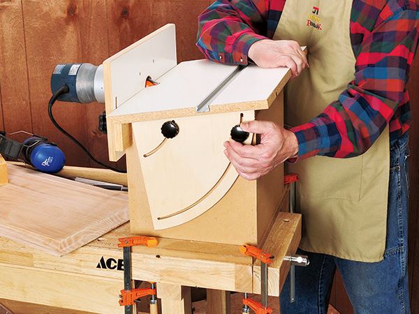
Sure, a regular router table that mounts a portable router vertically is great for all kinds of shaping jobs. But a router table that mounts the router horizontally is even better for tasks such as panel raising, joinery cutting and other shaping jobs where you’d rather have the work flat on a table than run it vertically against a fence. But this horizontal table has a versatile twist: its table tilts, allowing you to do a variety of work that’s difficult or impossible on a regular flat router table. For example, you can shape angled tenons on the ends of aprons or stretchers that join the splayed legs of a stool or chair. You can also use the tilted table to rout slots for splines that join beveled parts — say, the sides of an octagonal planter. Best of all, by changing the angle between the profile of the bit and the workpiece, the tilt-top lets you rout a variety of new shapes from the router bits you already own!
Versatile Design
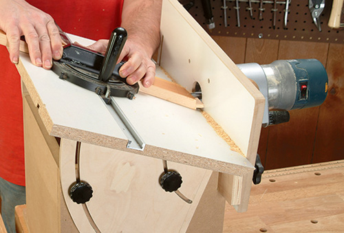
Happily, this unique table isn’t difficult to build, doesn’t require much in the way of materials and is compact, so you can easily stow it away when it’s not in use. The table has a cubical base with an oversized bottom that makes it easy to clamp the device atop a bench or work table. A pivoting router plate mounted to a crossmember on the base provides a mount for just about any standard router.
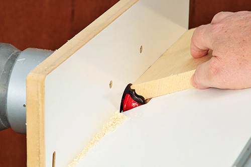
Pivoting the plate adjusts the bit’s cutting depth up and down (because of the horizontal orientation of the table, the router’s regular bit depth adjustment changes the width of the cut). The table’s top is attached to the base via a pair of plywood compasses, each with a pair of radiused slots that allow the top to tilt from flat to 45 degrees. A slot in the top accepts a standard miter gauge, which is useful for end-routing.
Kicking Off the Construction Process
To start construction, make the table’s base from 3/4″ MDF or particleboard. Cut out an 18″ x 12″ bottom, three 12″ squares for the front and sides and a 12″ x 3″ wide strip for the bottom rear (pieces 1 through 4). On the band saw (or with a jigsaw), cut a 3″ high, 3/4″ deep notch at the top back corner of each of the two sides for the crossmember that supports the router plate (cut the notch slightly shallower, if your crossmember stock isn’t fully 3/4″ thick). Make sure the notches’ edges are nice and square. Now drill a pair of 3/8″-diameter holes through each side piece, located as shown in the Drawings.
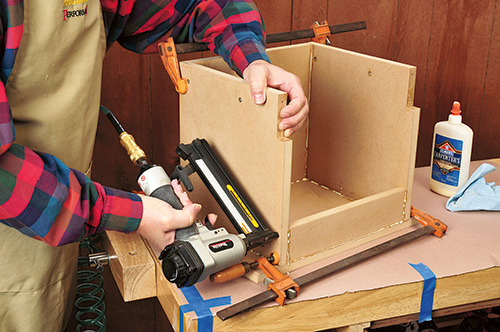
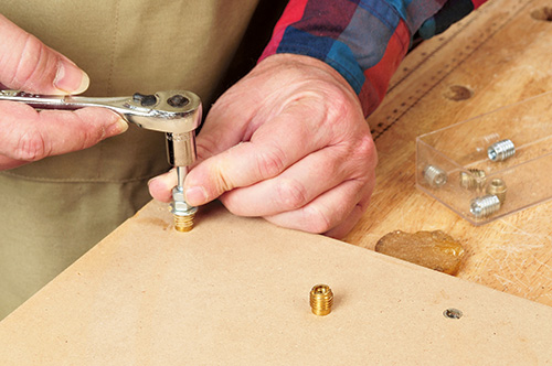
These are for studded hand screws that will attach the tilt-top to the base. Install a 1/4″ threaded insert in each of these holes, using a short 1/4″ bolt, two nuts and a ratchet wrench to drive them in place. Glue and nail (or screw) the sides of the base together, with the bottom strip at the lower edge of the cube. Center the sides on the base’s bottom piece and glue and nail them in place, making sure the assembly is square and that all the edges are flush.
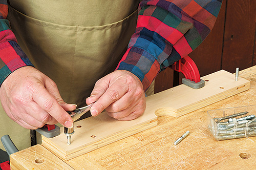
Cut the router table’s 3″ x 18″ crossmember (piece 5) from a piece of good quality 3/4″ plywood. Band saw or jigsaw a semi-circular hole at the center of the crossmember’s top edge to provide clearance for the router bit. Next, drill a pair of 7/32″-diameter holes, positioned 16-1/2″ apart, as shown in the Drawings. These holes are for the two 1/4″ x 1-1/2″-long hanger bolts that attach the router pivoting plate to the base. Hanger bolts have a wood screw thread on one half and a machine thread on the other. To install them, lock a pair of 1/4″ nuts together (with a washer between them) on the bolt’s machine threaded end, and drive the screw-thread end into the holes. Now glue and screw the crossmember into the notches on the base, centering it side-to-side.
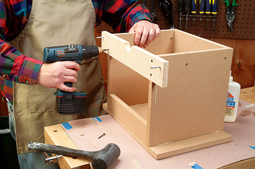
The router plate consists of two 18″-long, 9″-wide pieces sandwiched together: a 1/4″-thick plywood, melamine or tempered hardboard facepiece and a 1/2″-thick MDF or plywood backing piece (pieces 6 and 7). In the center of the face piece, drill a 2″-diameter hole for the router bit. Now remove the sub-base of the router you’ll use with the horizontal table, center it on the hole in the face piece, and clamp it down (make sure to orient the sub-base so that the router’s final mounted position on the router plate will locate the On/Off switch facing upwards, for easy operation). Go ahead and chuck a self-centering bit (these have a spring-loaded guide sleeve that centers the bit in a hole) in an electric drill and, using the subbase’s mounting holes as a template, bore the router mounting holes through the face piece. Countersink the holes for the mounting screws so their heads will be flush with the surface of the plate. After sawing a hole in the center of the backing piece large enough to clear your router’s base, carefully align and glue the backing and face pieces together.
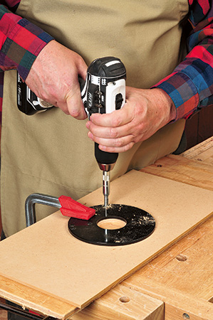
Tip: To keep two flat surfaces being glued up from sliding around when you apply clamping pressure, drive a couple of small brads in one surface, then clip them off nearly flush; the nibs “dig in” and keep parts from sliding.
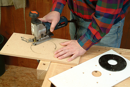
Next, drill a hole in the router plate for the hanger bolt that allows the plate to pivot (located as shown in the Drawing). Fit a router with a circle jig and 5/16″ straight bit set to cut all the way through the plate. Set the circle jig so that the distance between the pivot pin and the centerline of the bit is exactly 16-1/2″.
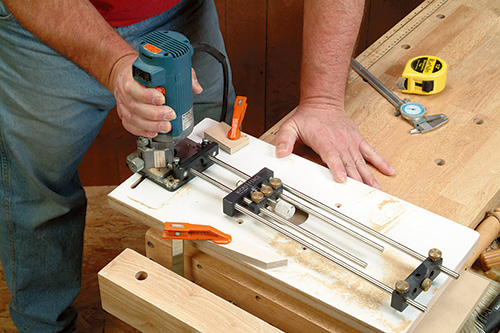
With the router plate clamped atop a wood scrap, rout the curved slot following the dimensions in the Drawings. Attach the plate to the crossmember with a pair of threaded hand screws.
Getting to Tilt
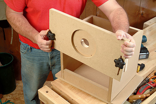
The two compasses (pieces 8) that support the table top and allow it to tilt are the most complicated part of the build. The compasses are necessary, because they allow the top to tilt without being hinged on the router plate — an arrangement that wouldn’t allow the plate to adjust up and down for depth of cut. Both compasses are sawn from a single 11-1/4″-wide, 20″- long blank of 1/2″ plywood, laid out as shown in the Drawings. Use a good quality plywood, such as Baltic birch. Each compass has a pair of semicircular slots routed through it, located as shown in the Drawing. Screw the blank temporarily atop a scrap piece of 24″ x 14″ (or larger) plywood or particleboard. As the actual pivot point of the tilt-top is located beyond the corner of each compass, where the front of the router plate and top meet, you must screw a pair of scrap blocks to the plywood to provide a pivot point for layout and slot routing. The 1/2″ x 4″ x 1-1/4″ scraps are positioned at opposite corners of the blank, as shown in the Drawing. Use a compass set to a 12″ radius to mark the outer edge of each compass. Mark the stop lines for the slots, as shown in the Drawings.
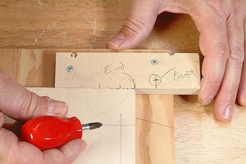
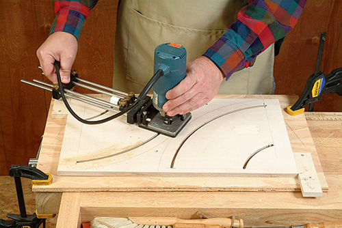
It’s easiest to use a plunge router to cut the two radiused slots in each compass. But by using a little finesse when starting and stopping slots, a regular router or laminate trimmer will work. For the smaller slots, set your router’s circle jig so that there’s 5″ between the pivot point and the centerline of a 5/16″ straight bit. Rout these slots on each of the two ends of the compass blank, starting and stopping the bit at the lines you marked. Now reset the circle jig to an 11″ arc and rout the two larger radius slots. Band saw the compasses from the blank by cutting out their curved outside edges, and sand them smooth.
Cut the table’s 14″ x 22″ tilt-top (piece 9) from 3/4″ melamine or MDF stock, then bevel the lower edge of one of its long edges at a 45° angle (see the Drawings). The bevel allows the tilted top to clear the base. Now measure the exact width of the table’s base you assembled earlier (it should measure about 13-1/2″ wide). Using a 1/2″-wide dado set in your table saw (fine-tuned to fit the exact thickness of the plywood compasses), plow two 3/8″-deep dadoes across the narrower dimension on the underside of the top. Space the slots so that their inside-facing edges are as far apart as the width of the base. This will ensure that the inside faces of the compasses will fit snugly against the sides of the base.
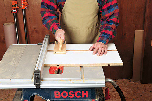
Next, set your table saw’s dado set to plow a miter-slot groove into the top surface of the top, located as shown in the Drawing. You can cut a 3/4″-wide, 3/8″-deep groove to fit the bar of a standard miter gauge. Alternatively, you’ll get a more accurate and wear-resistant miter gauge fit by installing a length of aluminum miter slot track. This requires dadoing a larger slot, sized to fit the track you use.
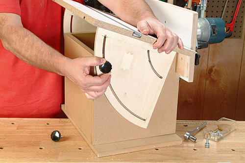
Glue the two compasses into the dadoes in the table top, aligning each compass’s square corner flush with the lower corner of the top’s beveled edge. Set the top/compass assembly on the base, bringing the top’s beveled edge flush to the router plate. Screw the studded hand screws into the threaded inserts.
Putting the Router Table to Work
To use the router table, set the table to the desired degree of tilt and tighten the compass hand screws. Next, set the width of cut the bit will take using your router’s depth of cut adjustment. Finally, set the actual depth of cut by loosening the hand knobs on the router plate and pivoting the plate up or down. Lock it in place.
Now you’re ready to perform your basic run-of-the-mill routing jobs, plus a host of technically difficult angled cuts and modified profiles that your ordinary router table just can’t do.
Click Here to Download the Drawings and Materials List.
Hard-to-Find Hardware:
Threaded Inserts (8) #28803
Hanger Bolts (8) #24406
5-Star Knob (4) #58085
5-Star Stud (4) #58261
Miter Track #23880
