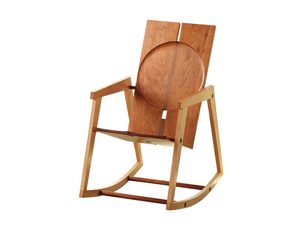
I have always wanted to design a rocking chair that I could claim as uniquely my own. My chair would have clean lines, broad planes and intriguing negative spaces. It’d definitely be modern. Here is what I’ve come up with.
I first considered the wood choices and decided to use slightly contrasting woods. Since walnut and cherry complement each other, and over time the contrast between the two lessens, I thought this would be a good choice for the seat. I felt the framework that supports the seat should have more contrast, because of the significant role it plays, so for these components I choose European beech. This beech is light colored, and its nondescript grain lines enhance the seat area while bolstering structural integrity to the side assemblies.
Next, I started thinking about the overall design concept. A few pencil sketches of a rocker with a seat that was supported and separated from the side assemblies by wooden dowels developed. The sketches were captivating enough to lead me to build a model. After studying the model for a while, I made a few refinements and was ready to begin.
Building the Side Assemblies
The rocker is broken down into two basic subsections: the seating components and the side assemblies. I chose to start with the beech and the side assemblies first.
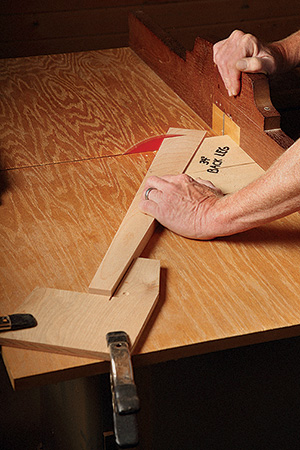
I selected beech with the straightest grain I could find to enhance these slender parts. I jointed and planed 4/4 beech boards to 7/8″ thick.
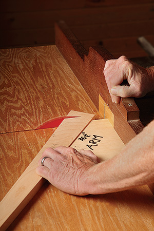
Each side assembly consists of four parts: an arm, two legs and a curved rocker. For easier processing, I drew a full-size side assembly on a piece of scrap plywood to determine the actual sizes of these parts.
If you choose to make this chair, I suggest you take the time to draw out the side assembly as I did. It is a valuable reference as you are cutting these parts.
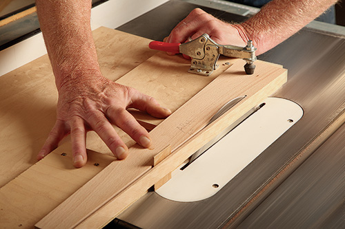
The arms and legs all taper along their length at a 4˚ rate. I did this with a shop-made tapering jig on the table saw.
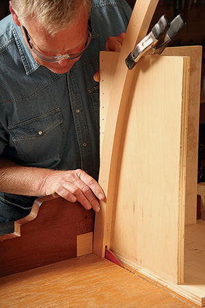
Then it was on to the next cuts on the arms and legs, cutting them to length with their ends set to the proper angles (see the Drawings). Referencing my full-size drawing, I was able to use it to make a template out of MDF for laying out and shaping the curved rocker.
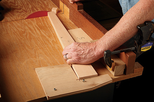
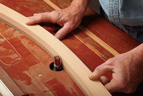
After roughing out the rockers at the band saw, I attached the template to the rocker with double-sided tape and used a pattern bit to refine the rocker’s shape. The rocker connects to the legs with bridle joints.
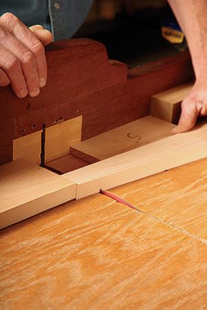
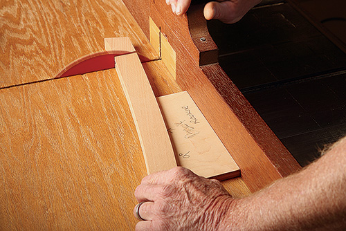
I used a tenoning jig on my table saw to cut the open mortise of the bridle joints into the rockers. Next, I cut the full-width tenons on the end of the legs.
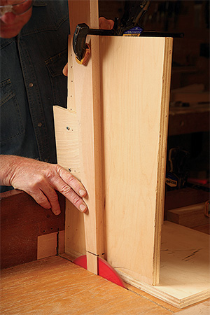
Note: use a scrap piece of the leg stock to make sure you have the angle correct.
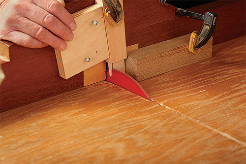
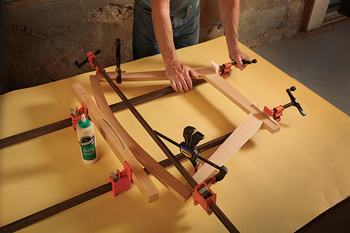
I glued the side assemblies up in three stages, allowing ample drying time for each stage. For the first stage, I glued the arms to the back legs at the angles shown in the Drawing.
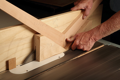
Then I carefully sliced a spline kerf into these joints on my table saw. I machined spline stock to properly fit the openings and glued them in place with the grain running perpendicular to the joint line.
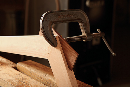
To get ready for the next joints, I dry-assembled the legs to the rockers in order to lay out where the tenon and mortise will meet on the front leg and arm respectively.
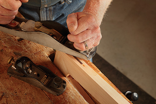
As you can see, the angle at which the leg abuts the arm requires that you raise the tenon at an angle from the top of the leg.
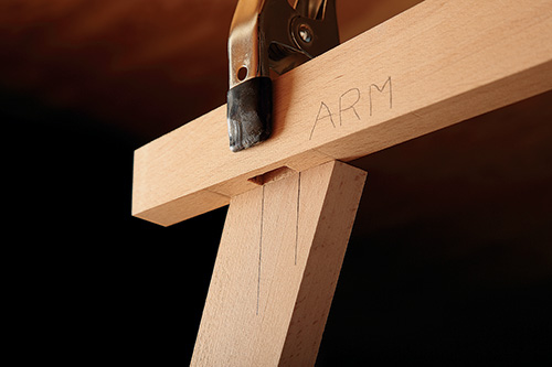
To do that, I first established the shoulders of the tenon joint by nibbling away material on the table saw.
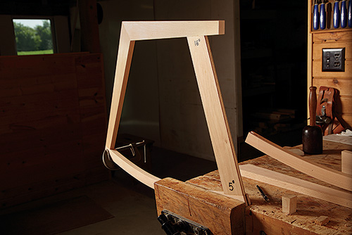
Then I used a fine-toothed back saw to saw the tenon cheeks. I recommend taking your time through this process. Once you have all the joints fitting well in the side assemblies, you are ready for the final stage of glue-up.
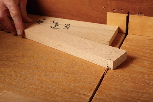
After the glue cured for 24 hours, I sanded the subassemblies smooth. Then there were a couple of holes to bore that would later capture the stretchers. I used Forstner bits at the locations shown in the Drawings.
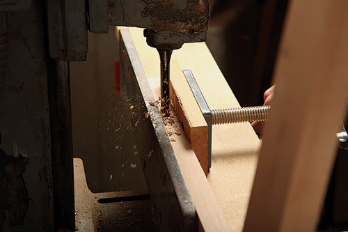
When drilling for the seat support dowels on the inside of the assemblies, a smaller diameter 5/8″ bit is used as compared to the one used on the outside for the dowel covers.
The final holes to bore are pilot holes for hanger bolts that join these subassemblies to the seat/back subassembly. With that task done, I was ready to move onto the seating components.
Making the Seat and Back
Building the seating subassembly is where some hand tool use and edge refinement is critical in order to achieve a fine-furniture look. The cherry boards that make up the back and seat should be heartwood on both faces because they will be viewed from all sides. In my opinion, any sapwood detracts from the overall design, so choose your boards carefully.
Surface the cherry to a final thickness of 7/8″. Leave the boards longer than final dimension by a few inches just in case you need to redo the box joints, but it is OK to rip them to their final width.
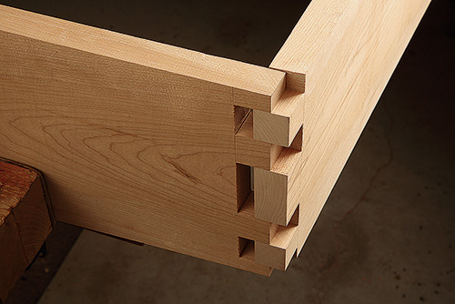
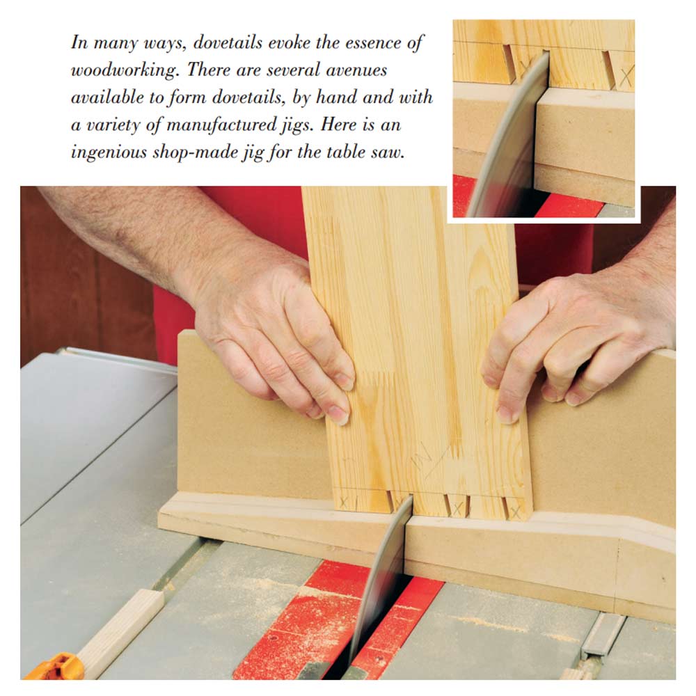
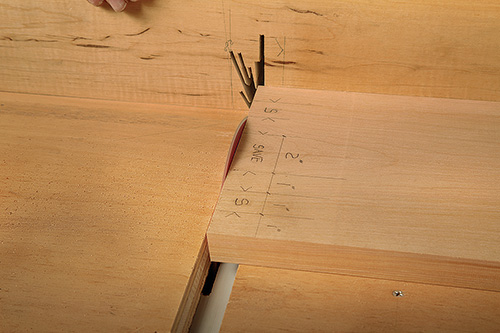
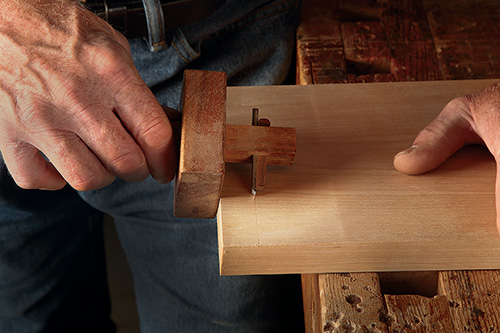
Because the box joints between the seat backs and seats are cut at an angle, I first crosscut the boards with the table saw blade tilted 5°. Before you start cutting the box joints, scribe a line with a marking knife on the outside of the cut to prevent chip-out.
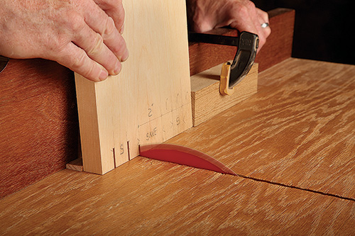
Now lay out the box joint pattern onto the seat pieces. I used my regular crosscut jig to make the box joints, but by inserting a spacer behind the board, I could consistently hold the 5° angle during the cuts without a problem. With that ready to go, I carefully removed the waste in a series of side-by-side cuts.
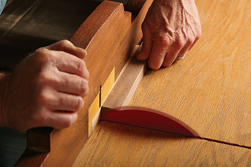
Next, transfer box joint spacing to the cherry backs using seat boards laid against them in their final positions. Then follow the same cutting procedure as with the seats. Take note that the 5° angles on the terminal ends of the cherry boards are cut first, then position them onto the crosscut jig in the same way.
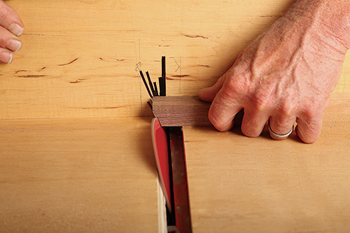
If you take special care in setting your stops accurately, then you really only have to cut one board with great care. Cut one joint and test its fit before moving on to the next one. This will reduce the chance of all the joints being off just a little. In other words, you may have to adjust your initial pencil marks as you proceed.
Although it is subtle, if you look at the Drawings, you will see that the seat and back pieces are slightly tapered on their inner edges. Once the box joints fit, you can rip your boards using an angle jig — this will remove about half of your outside box joint Take note that your backs and seats are cut at different angles because the backs are longer than the seats.
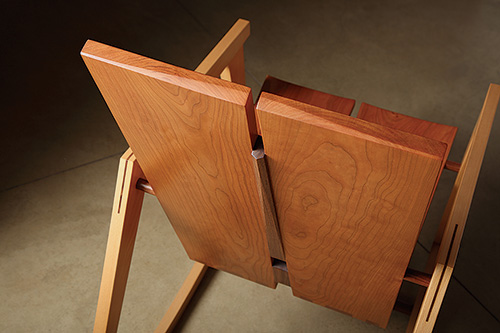
Now you can cut the seat and backs to length and sand all faces to 400 grit. Joint the inside edge using a jointer or hand plane to promote an optimal glue joint for the seat and back centers later on. Gluing up the seats to the backs, you need to apply pressure evenly so the angled box joints seat themselves properly.
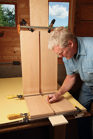
This will take some dry assembly and clamping mock-ups before you are ready for glue-up. Then drill counterbored holes into the edges of the box joints and drive #8 x 1-1/2″ screws into them. Cut a 3/8″-dia. walnut dowel into plugs to cover these screw heads, and sand the plugs flush to the cherry.
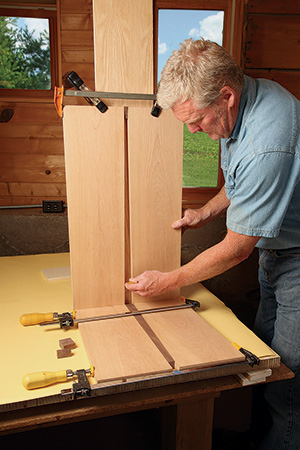
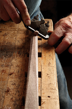
Again, look to the Drawings and you will notice that there are walnut seat and back centers that join the two seat subassemblies together. These pieces are tapered to mirror the angles you just cut into the back and seat pieces. In addition to their tapers, I shaped their back faces with a spokeshave to provide more visual accents to the chair. The walnut should be ripped using the same jig you used for cutting the cherry.
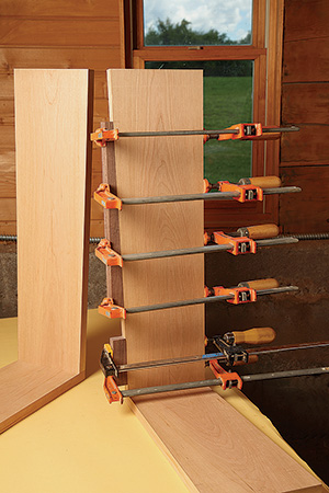
Once you’ve tapered the center pieces, test their fit to prepare for glue-up. If you are satisfied with this positioning, cut them to length. Note that three of the crosscuts are made at a 5° angle. The walnut parts, prior to glue-up, need to be sanded on the end grain, and the 16″-long centers need additional shaping. I call this shaping a disappearing chevron because it transitions from one end to flush with the cherry backs. Since the angled parts will slide easily when glued, glue the walnut centers to one side assembly first.
Shaping and Bolting It All Together
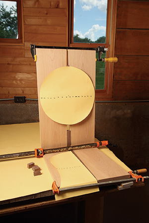
The final shaping on the back and seat are recesses that provide comfort and visual interest. With colored pencil (white so it’s easy to see), I drew the areas to be carved out on seat and back. Then I used a 4″ grinder attachment from King Arthur Tools to sculpt and shape the two recessed areas, being careful not to go over my pencil marks. Sand these areas, staying inside the pencil marks to optimize the refined transition from the flat plane to the contoured areas. Then sand these recesses up through the grits to 400, working carefully.
The last stage is attaching the seat to the side assemblies. This is a critical step and requires some adjustment. First, mark the hanger bolt locations on the back of the chair subassembly. Drill a 5/8″-diameter hole 1/8″ deep. Then center a deeper pilot hole inside this support dowel recess for threading a 1/4″ hanger bolt.
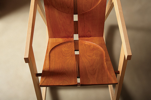
Lay the chair/seat subassembly on its side and place the rocker assembly roughly in place on top of it. Insert a 1/4″- diameter dowel through the bolt location in the rocker assembly and into the hole you just bored.
Now rotate the rocker assembly until the bolt hole in the front leg is centered on the seat edge. Mark that location and drill it for the hanger bolt as you did earlier on the back section. You’ll need to repeat this process on the opposite side of the seat/back subassembly.
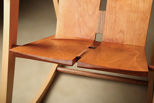
Thread the hanger bolts into the seat/back subassembly. Take special care here so you do not split the cherry. Now make the seat support dowels by drilling 5/16″-dia. holes through 5/8″ walnut dowels (center the holes on the dowels). Cut the dowels to length to slip over the hanger bolts. Check to see if your hanger bolts stick out the right length by slipping walnut dowels over the bolts and fitting the side assemblies in place. Make sure enough threads are exposed for threading on a washer and jam nut. It’s important to use a jam nut instead of a regular nut because the jam nut is about half as thick. This makes it possible to have enough room to cover the hardware with walnut dowel plugs.
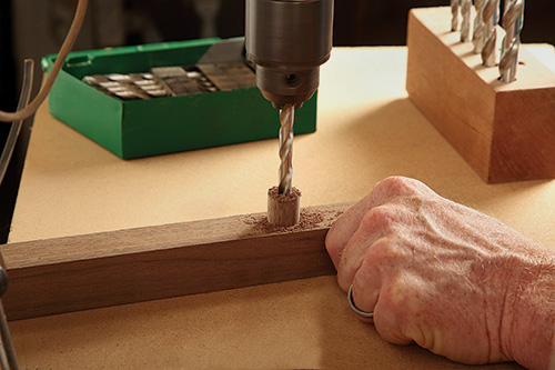
When you are satisfied with the hanger bolts at all four locations, remove the seat from the side assemblies and put a drop or two of super glue next to threads of each hanger bolt to ensure it cannot back itself out over time. This is probably overkill, but it would be difficult to remove the walnut dowel plugs and re-tighten after the chair is complete. Reassemble the chair again and tighten the jam nuts. To accurately take measurements for the two long 1″ walnut dowel stretchers that are located between the front and back legs, it’s a good idea to use some spacers here and light clamping pressure on the side assemblies to check for square.
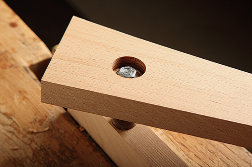
Take measurements at the top and back of side assemblies to see if they are all the same. Then take measurements for the dowel stretchers, being certain to account for the shallow 1″ counter bore depths. Finally, loosen the jam nuts enough so that you can easily position the stretchers, add a little epoxy glue to the stretchers’ end grain, put them in place carefully, and tighten the jam nuts. Now drive wood screws through the rockers and into the ends of the stretchers to lock them in place. Cut walnut dowel plugs for all eight counterbores. Glue them in place and sand them flush. The rocker is now ready for finish. I used Sam Maloof poly/oil to bring out the rich luster of the hardwood. Cheers!
Click Here to Download the Drawings and Materials List.
Greg Wood is a professional woodworker from Howard Lake, Minnesota. You can view his work at gregwoodfurniture.com.
