I have a deep admiration for the long, low elliptical table designed by Ray and Charles Eames back in 1951. With its minimalist design and mixed materials (metal, plywood, laminate), the husband and wife team’s iconic piece captures the spirit of its age. The elliptical top appears to float over the double pedestal wire base, the top’s beveled edge drawing attention to the contrast between laminate and substrate. Its popularity is perennial — Herman Miller still makes it over 60 years after its original release. Unfortunately, at only 10″ high, the table is a little impractical for use as a coffee table; 18″ or so is a more useful height.
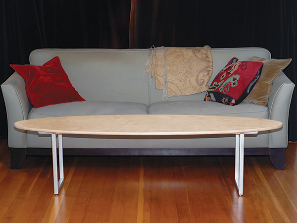
In building a variation on the design, my challenge was to preserve the appeal of the original while producing a practically sized table I could build in a modestly equipped shop. Welding a steel rod base is beyond both my tooling and my ability, but I knew from previous experience that you can cut aluminum with carbide blades and bits and then glue it with epoxy. After visualizing several alternatives in SketchUp, I settled on the design presented here: a 22″ x 72″ elliptical plywood top over a metal trestle base composed of two rectangular frames bridged by two stretchers with beveled ends. To foster the illusion of a floating top, the stretchers are set back from the side of the frames and joined to the frames with shallow half laps.
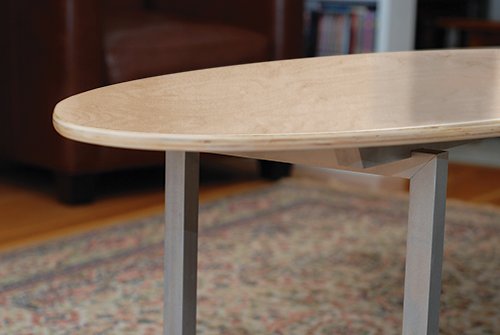
The spare design doesn’t require much in the way of materials and goes together quickly. Building the table provides a useful introduction to cutting an elliptical top and using tools you probably already have to incorporate metal into your woodworking, expanding your arsenal of techniques.
Begin With a Solid Foundation
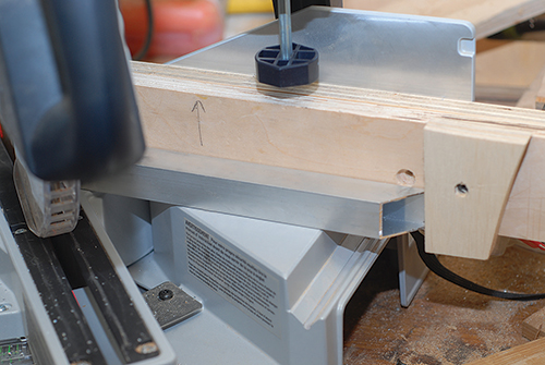
Each table leg consists of a rectangular frame of 1″ square aluminum tubing joined by miter joints, with the miters reinforced with short lengths of wood. Begin by cutting the four short and four long sides of the frame on the miter saw. A carbide blade will make quick work of the aluminum tubing, but working with metal instead of wood requires extra care: clamp the workpiece down, take cuts slowly, and let the blade come to a complete stop before unclamping the pieces. A stop block on the miter fence makes for easily repeatable cuts.
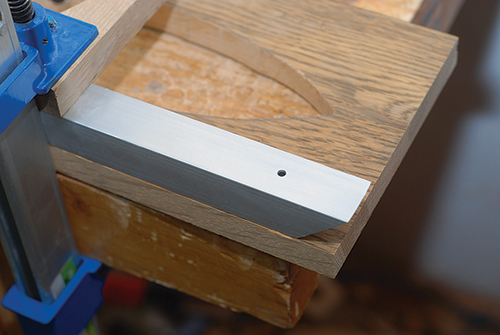
Before gluing the frames together, you’ll want to drill pilot holes in the two top frame rails. Mark the location of the holes 1-1⁄2″ from each end (measured from the long edge of the miter) and centered on the width of the aluminum tubing, then drill through the top and bottom of the tubing with a bit sized to clear the threads on the screws you’ll use to anchor the whole to the top (I used a 3/16″-dia. bit). Now drill clearance holes through the bottom walls of the top rail tubing, sized to accommodate your screw heads. Deburr any rough edges with a file or sandpaper and prepare the frame for assembly.
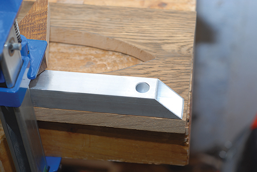
The thin walls of aluminum tubing don’t offer a lot of surface area for glue, so I used a short length of wood to reinforce the joints, ripping scrap stock so it just slides inside the tubing. This stock is cut into 1-1⁄2″ lengths and scuff-sanded with 80-grit to give it some tooth. The faces of the miter joints and inside surfaces of the frame parts are sanded as well just before assembly. I glued up the frames in stages, first joining one rail and one stile to form an L-shaped subassembly using a corner clamp. These subassemblies are then joined to form the rectangular frame.
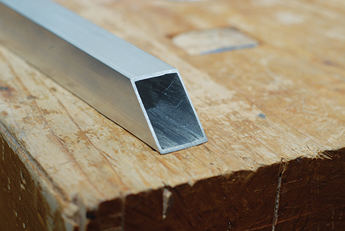
Gluing aluminum is much like gluing wood, with epoxy standing in for PVA or hide glue. Dry-assemble the parts to verify their fit and rehearse how things go together, then apply glue, clamp things up, and let the glue dry. I mixed J-B Weld™ epoxy per the manufacturer’s instructions and applied it to the end of one miter and a thin layer to the first half-inch or so of the inside of the tube.
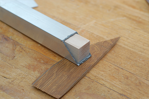
I then inserted a wood block in the tube end and applied epoxy to the inside of the other half of the joint. After bringing the two frame parts together, clamp the subassembly firmly. I scraped off the squeeze-out with a putty knife and let the joint cure overnight.
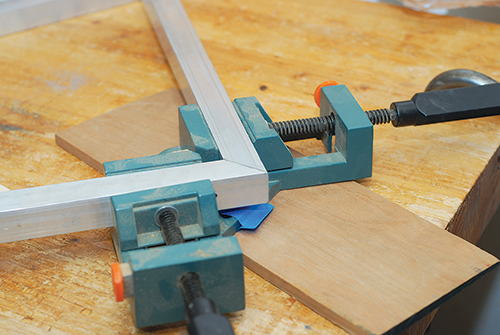
Two of these L-shaped subassemblies form a single frame. The frames are glued up in the same way as the subassemblies, although you’re working with two corners, not just one. If you’ve pre-drilled screw holes in your frame tops, take care not to glue up two tops in the same frame. After the epoxy has cured, use a razor blade to remove any remaining squeeze-out, and set the frames aside for sanding, later.
Making the Stretchers
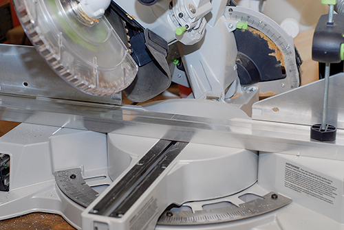
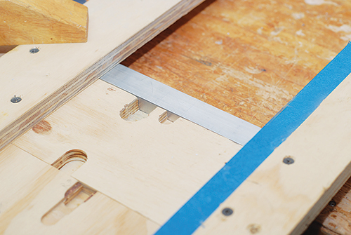
Two long stretchers form the rest of the base. Cut them to length, beveling each end to 30˚, then mark the locations of half-lap joints, beginning 1-7⁄16″ from each end. Each notch is 1″ wide x 1/4″ deep. I used a 3/4″ straight bit in a router guided by a simple dado jig to make these cuts. It’s tempting to clamp the stretchers together and gang-cut the joint, but I’ve had better luck cutting them individually. Because the cut isn’t removing much material, I made it in a single, slow pass with the router set to a low speed after clamping the jig and stretcher firmly to my benchtop.
Once the joints are cut, you can drill clearance holes and pilot holes for the screws used to secure the stretchers to the top. I drilled one hole at the center of each stretcher, then two more spaced evenly between the center hole and half-laps (approximately 12″ on center). I first drilled pilot holes all the way through the bar at each location with a small-diameter bit (3/16″), sized just larger than threads of my screws (note that, if you use solid stock for the top, you’ll want larger holes to allow for movement of the top), then a clearance hole at each location in just the bottom face of the stretcher. This hole needs to be large enough to accommodate the screw head size.
The last holes you need to drill are for the screws joining the frames to the top through the stretcher. Sized to accommodate your screw threads, these holes are centered on the notches in the stretcher.
To give the stretchers a more refined appearance, I epoxied thin caps to the ends of the stretchers to cover them. I made these caps using a side wall ripped from a scrap length of tubing. Because the stretcher ends don’t bear weight, I didn’t reinforce these joints with a wood plug. Instead, I simply scuff-sanded the beveled edges and caps, then applied epoxy to the bevels and pressed the caps into place.
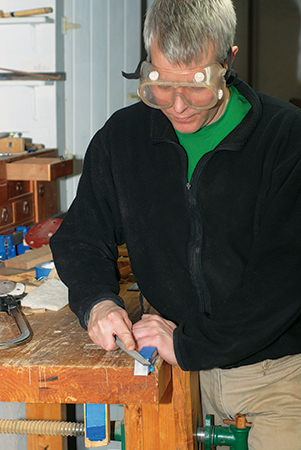
After the epoxy cured, I scraped away glue squeeze-out and trimmed excess metal off with a hacksaw. Then I filed the edges of the caps flush with the sides of the stretchers. Once the stretchers are capped, they can be put aside until you’re ready to finish the base.
Topping Things Off
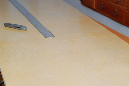
Like many Mid-Century Modern designers, the Eameses experimented with new materials. Their elliptical top featured a laminate layer over a plywood substrate. You could use a melamine-faced plywood if you wanted to follow suit, but making the top offers some opportunity for your own experiments. Consider an exotic veneer, solid wood or even solid surface.
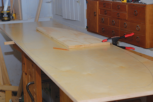
To coordinate with the light, silver tone of my brushed aluminum base, I chose a plywood with a birch veneer. My own experiment was limited to using prefinished plywood. There are several ways to cut an ellipse. You can use a string and screws to define the loci and radii of the shape, then trace the edge of the ellipse with a pencil. Cut the ellipse out and sand it to shape. You can also rout one using a two-axis jig.
These jigs can be made in the shop or are available commercially. I found it easiest to make a rigid template and rout the ellipse that way. Because an ellipse is symmetrical on two axes, you only need a quarter template instead of the full elliptical shape. I created a pattern in SketchUp and printed it out, then traced it onto some 3/4″ plywood, sawed close to my lines on the band saw and sanded the template to final shape.
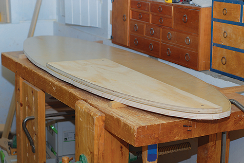
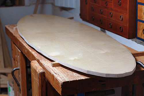
With the template ready to go, cut a slightly oversized piece of plywood and mark center lines on its long and short axes on the bottom of the blank. Use these center lines to position the template and trace the ellipse. After marking the full shape, cut close to the perimeter using a band saw or jigsaw. Then, with a flush-cutting bit in the router, use the template to rout the top to final shape. You could stick the template to the top panel with double-sided tape for routing, but I simply screwed through the template into the bottom face of the top — those holes won’t show from the top.
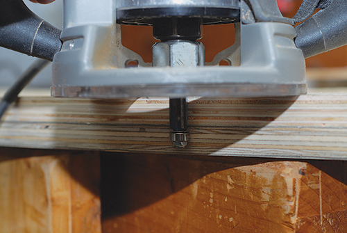
Rout the first quarter arc of the ellipse, then reposition the template and repeat three more times. If your cuts don’t meet perfectly, you can fair them with a sander. Once you’re satisfied with your elliptical top, decide on an edge treatment. The Eames table features a single bevel running the thickness of the top; I eased the top and bottom edges with a 1/4″ roundover bit instead and sanded this profiled edge up to 220-grit.
Finishing Up
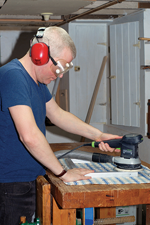
Although they are made from very different materials, finishing both the top and the base begins with sanding. Because I used pre-finished plywood, only the exposed edges of the plywood needed finishing. After filling a couple of voids in plys of the exposed edge and giving things a quick sand, I applied a couple of coats of a satin water-based polyurethane, lightly sanding between coats. Your finish schedule may vary depending on your choice of materials.
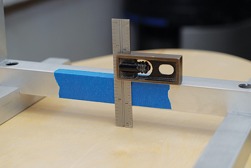
Aluminum lends itself to a number of finishes, though some, like anodizing or powder coating, might be better left to the professionals. But a sanded or painted base is easily achievable in the home shop. You can create a surprising number of effects simply by sanding — varying grit or direction can dramatically alter aluminum’s appearance from brushed finishes to a mirror-like polish. Experiment on scrap tubing to find an effect you like. For a brushed appearance, I sanded the base with 220-grit paper in a random-orbit sander, changing the paper relatively often and wiping the base clean with a damp rag after sanding.
Whatever finish you choose, you may want to install leveling feet at each corner of the bottom rails in the frames. These feet prevent the sharp edges of the base from scratching the floor.
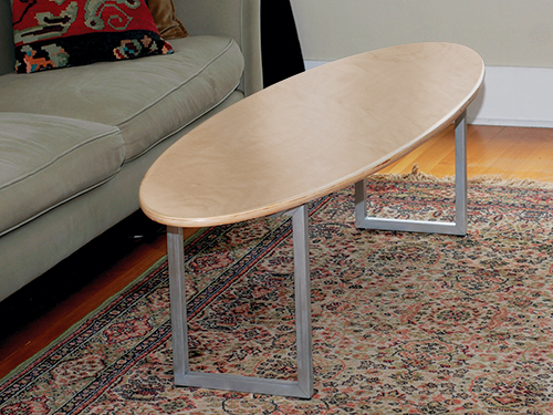
To wrap things up, invert the top, and fit the base frames into the notches in the stretchers. The frames overhang the stretchers by 1″. Mark the center points of the top rails and stretchers, and line these center marks up with the center lines on the table. Attach the base with panhead screws driven through the clearance and pilot holes. Once you’ve joined the base to the top, the table is ready for its new home. Put up your feet and hang 10 on your new Mid-Century Modern coffee table.
